

Abstract
Synchrotrons and free electron lasers are unique facilities to probe the atomic structure and electronic properties of matter at extreme thermodynamical conditions. In this context, 'matter at extreme pressures and temperatures' was one of the science drivers for the construction of low emittance 4th generation synchrotron sources such as the Extremely Brilliant Source of the European Synchrotron Radiation Facility and hard x-ray free electron lasers, such as the European x-ray free electron laser. These new user facilities combine static high pressure and dynamic shock compression experiments to outstanding high brilliance and submicron beams. This combination not only increases the data-quality but also enlarges tremendously the accessible pressure, temperature and density space. At the same time, the large spectrum of available complementary x-ray diagnostics for static and shock compression studies opens unprecedented insights into the state of matter at extremes. The article aims at highlighting a new horizon of scientific opportunities based on the synergy between extremely brilliant synchrotrons and hard x-ray free electron lasers.
Export citation and abstract BibTeX RIS

Original content from this work may be used under the terms of the Creative Commons Attribution 4.0 licence. Any further distribution of this work must maintain attribution to the author(s) and the title of the work, journal citation and DOI.
1. Introduction
Science under extreme conditions is a vibrant field of research, which has been notably fostered by the construction of large x-ray user facilities. This is because the major challenges of in-situ extreme conditions experiments can be largely overcome using bright x-ray radiation. In static compression studies, micrometric size samples are enclosed in highly absorbing sample environments (i.e., diamond anvil cell (DAC), Paris–Edinburgh press, large volume presses). High brilliance, tightly focused, x-ray beams are required to probe the state of matter in these small volumes at the extreme conditions (figure 1). In dynamic shock-compression experiments the state of matter at extremes is probed during nano-second lasting propagation of the shockwave, urging thus for short (femto/pico-second), coherent and bright x-ray pulses.
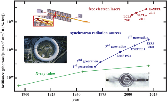
Figure 1. Historical evolution of x-ray brilliance over time and development of new x-ray sources. FELs values are given for the peak brilliance, during one pulse (table 1).
Download figure:
Standard image High-resolution imageSince large x-ray user facilities offer these unique capabilities to a large community of scientists, high-pressure research experienced a strong and highly successful development in the past three decades. For example, synchrotron-based x-ray diffraction was used back in 1996 [77] to measure the equation of state of single crystal hydrogen at pressures above 1 Mbar, a bearing stone in the search of one of the most challenging scientific questions, namely the metallization of hydrogen [5]. Similarly, the fundamental question of pinning the iron melting temperature at Earth-core conditions could be answered using state-of-the-art synchrotron x-ray measurements [3, 78]. Other examples are the experimental proof of chemical reactivity and compound formation of xenon (a noble gas, chemically inert at ambient conditions [28]), with oxygen at 90 GPa and 3000 K, the discovery of complex carbon chemistry (e.g. [19, 23, 119]) and molecular to atomic dissociation in high energy density (HED) systems (e.g. [62]). A further milestone in applied materials is the capability of synchrotron x-rays to reveal superconductivity at extreme conditions, for example the direct observation of the Meissner effect, i.e. the expulsion of an external magnetic field, in H2S at 150 GPa and temperatures up to 140 K [131]—or the disclosure of cavity collapse in model systems in relation to hot spot formation and ignition mechanisms in energetic materials [36].
'Matter at extreme conditions' was one of the scientific drivers for the construction of low emittance 4th generation high-energy synchrotron sources and of hard x-ray free electron lasers. These facilities deliver an unprecedented brilliance, over 105 to 1015 times that of 3rd generation synchrotrons for the European Synchrotron Radiation Facility Extremely Brilliant Source (ESRF-EBS) and the European x-ray free electron laser (EuXFEL) respectively (figure 1), and offer optimized compression setups on the beamlines, enabling to bridge the gap between two initially independent communities of extreme conditions scientists: those using static and dynamic compression.
This contribution aims at defining the current state-of-the-art at high-energy x-ray user facilities and at discussing the new research opportunities that will emerge from the complementarity of these large instruments. We focus here on two new, outstanding user facilities: the first high-energy x-ray diffraction-limited storage ring: the ESRF-EBS and the first high-energy high-repetition rate (MHz) x-ray free electron laser: the European XFEL (EuXFEL) [24]. In the second chapter, we will provide the main facilities and beamline characteristics at both ESRF-EBS and EuXFEL (tables 1, 2 and A1, appendix). The third chapter is dedicated to examples of scientific applications and is followed by the last and fourth chapter, which aims at giving an outlook to future developments at large x-ray facilities worldwide and their subsequent upgrades.
Table 1. Generalized x-ray beam properties and parameters at ESRF extreme conditions beamlines and HED instrument at the EuXFEL.
| Parameter | ESRF EBS | European XFEL (HED) |
|---|---|---|
| Energy | 2–60 keV | 5–25 keV |
| Pulse length | 100 ps | <100 fs |
| Brilliance (phot/s/(mm2 /mrad2 /0.1%) | 1021 | 1033 (peak value) |
| 1025 (average value) | ||
| Flux | 109
ph/pulse (max) | 1011 –1012 ph/pulse |
| 1013 –1014 ph/s (on target) | (on target) | |
| Bandwidth | 1%–3% of the central energy value | ∼0.3% for SASE |
| ∼0.01% (seeded beam) |
a.Estimated flux on target for EBS beamlines ID24 HPLF and ID19. Attenuation from monochromators (Si 111), deflecting and focusing mirrors are taken into account. Note that for shock wave propagation measurements at ID19 the flux on the sample is ∼108 ph mm−2 (in 16-bunch mode operation). b.Measured SASE flux on target at HED instrument with 100% beam transmission (i.e. no attenuating filters along the beampath). Transmissions of CRLs and deflecting mirrors are taken into account. These values are given for one pulse per train. At the EuXFEL in 1 s 10 trains are produced with a maximal capacity to accommodate up to 2700 pulses per train (the nominal capacity is lower, ca 300 pulses/train).
Table 2. Overview of x-ray methods for extreme condition science supported at ESRF and EuXFEL (HED instrument).
| Method | Scientific interests | ESRF beamline | HED platform |
|---|---|---|---|
| X-ray diffraction (XRD) | Structural investigation of crystalline, amorphous and liquid materials (lattice spacing, density, texture, strain, pair-distribution function (PDF)). In situ detection of phase transition | ID15a | IC1 |
| ID27 | IC2 | ||
| ID06 | |||
| X-ray absorption spectroscopy (XAS, XRF) | Element selective. Studies of the local structure around specific atoms (EXAFS). Valence state (XANES). Diluted systems. Magnetization dynamics (fully polarized x-ray beam) | BM23 | IC1 (under develop.) |
| ID24 | |||
| ID12 | |||
| X-ray emission and Raman spectroscopy (XES, XRS) | Element selective. Sensitive to local electronic and magnetic structures (XES). Absorption edge of light elements in DAC using hard x-rays (XRS). Spin states (HS, LS). Ionization state of plasmas. Kβ , Kα -measurements, valence to core (vtc) | ID20 | IC1 |
| Inelastic x-ray scattering (IXS) | Phonon-dispersion studies at high pressure. Ionization state of plasmas. Electronic configuration | ID28 | IC1 |
| Nuclear resonance spectroscopy (SMS, NFS, NIS) | Element selective. Excitation of nuclear levels of probed atoms, which provide information on the local structure in the sample under investigation. Valence state (SMS, NFS). Ion temperature, acoustic waves (NIS) | ID18 | — |
| X-ray imaging (XRI) | Density (gradients) and internal morphology, in combination with phase contrast (XPCI) sensitive to surfaces and interfaces | ID19 | IC1 |
a.XRS in DAC is part of the future development plan at HED instrument, whereas XES is already available in combination with a four crystals Von-Hamos spectrometer. b.IXS in DAC is part of the future development plan at HED instrument. c.Static (i.e. DAC, Paris–Edinburgh press). d.Dynamic (i.e. shock dynamic compression).
2. Technical capabilities
The ESRF and EuXFEL offer diverse, highly versatile extreme conditions stations (tables 1, 2 and A1) which give access to a wide pressure (P) and temperature (T) domain (figure 2). These stations are compatible with a large range of high-pressure devices (as detailed hereafter), exhibit a high variety in beam properties (energy, beam sizes and pulse structure as reported in tables 1 and A1), are equipped with state-of-the-art detection systems (table A1) and provide a wide spectrum of complementary x-ray diagnostics to probe matter at extremes (table 2).
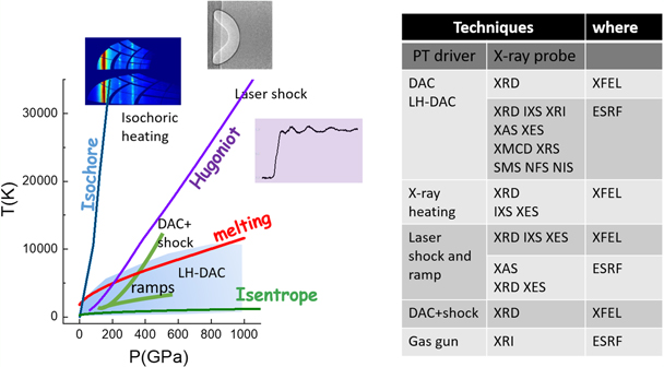
Figure 2. Schematic view of different conditions and techniques available at ESRF and EuXFEL. XRD data are from [139], XAS data are from [130] and XRI data from [36]. XRD coupled to shock compression is presently available at the ESRF only at moderate conditions on ID09 but it will be implemented as well as XRI and XES with HPLF-II. Shock compression at the EuXFEL will be available after installation of the DIPOLE laser and VISAR system (currently under re-installation and commissioning).
Download figure:
Standard image High-resolution imageSynchrotrons and XFELs are traditionally associated to static and dynamic compression experiments, respectively. 'Static' high pressure experiments are conducted at synchrotron facilities to take full advantage of the stable, high-flux and uniform x-ray beams, while 'dynamic' high pressure experiments are highly compatible with the beam properties provided by XFELs, consisting of high brilliance pulses of fs duration. Significant efforts have been made to enable static and dynamic studies on both facilities. This opens new scientific grounds thanks to the high degree of complementarity.
The available energy range, x-ray time structure and flux are the most important and the most complementary aspects of these two facilities (table 1). In the past, most investigations of high pressure phenomena have been conducted in 'static' systems relying on x-rays beams of very stable intensity, on timescales that span from milliseconds to hours or even days, thanks to novel current refilling modes. The pulsed nature of synchrotron radiation has more recently been exploited to investigate the dynamics of high pressure phenomena on timescales down to the ns. With the emergence of fs-pulsed x-ray sources, dynamic processes can now be extended to identify and characterize transient states. Both studies (static and dynamic) are often required to depict the underlying mechanisms of high-pressure phenomena.
Below we give a detailed description of the technical capabilities at 4th generation synchrotrons and XFELs, with the European synchrotron ESRF-EBS and EuXFEL as examples. The acronyms for the x-ray techniques mentioned in the text are explained in table 2.
2.1. ESRF
2.1.1. Static compression platforms
Research at extreme conditions in static mode has a long-standing tradition at the ESRF and profits tremendously from the extremely brilliant source upgrade (ESRF-EBS) that will provide up to a factor 5000 higher photon flux, a higher coherence which is advantageous for x-ray imaging and nanometric beamsizes on several beamlines (table A1). This evolution is concomitant with developments of highly optimized sample environments that allow covering a large P/T domain (pressures up to 6 Mbar and temperatures of several thousands degrees) with a high precision in terms of pressure and temperature stepping and determination [29, 41, 86]. At the same time the new source properties also allow studying materials at low x-ray energies down to 3 keV in DAC [141]. State-of-the-art devices include the toroidal DAC to reach multi-Mbar pressures [29], high pressure devices for imaging, stress and magnetic studies [63, 98, 101, 126] laser-heating devices [4, 58, 65, 86], cryogenic DAC cooling techniques [60] and resistively heated DACs [26, 112, 113], new anvils materials [32, 52, 53, 97, 112] and assembled gasket structures [110, 116]. In addition, new acquisition techniques have been developed to refine and enlarge the different probe techniques in order to extract more detailed structural and electronic information, such as multi-grain crystallography for diffraction [112], quick scan acquisitions for EXAFS [102] and advanced x-ray imaging techniques [106].
These decade-long continuous developments and investments have made high pressure research at the ESRF a world-recognized landmark providing data of highest quality and precision in static mode. Static synchrotron studies are highly complementary and often serve as a benchmark for the new emerging dynamic studies at the ESRF high power laser facility (HPLF) and XFELs.
2.1.2. Shock dynamic compression
Dynamic compression experiments are carried out at the ESRF coupled to XAS (ID24), XRD (ID09) and XRI (ID19) (tables 2 and A1).
The newly constructed high power laser facility (HPLF-I), currently under commissioning at ESRF, will couple a flash-pumped liquid-cooled Nd:glass 100 J laser (Amplitude Technologies), to the energy dispersive XAS beamline ID24-ED [94]. Velocity interferometer system for any reflector (VISAR) [7] and streaked optical pyrometry (SOP) will be used to respectively characterize the laser shock propagation and measure the temperature. A VISAR is capable to measure the velocity of a reflecting surface with ps temporal resolution and μm spatial resolution. Thus, depending on the experimental setup, the VISAR measures particle or shock velocities throughout the compression phase, which can be directly related to the pressure evolution of the sample.
The HPLF facility will be later extended to couple the amplitude laser to an adjacent beamline with the aim to implement XRD, XRI and XES techniques (HPLF-II). The increase of the laser energy to 200 J and use of its second harmonic are also foreseen as future upgrades.
Dynamic compression setups supplied by external groups have also been used in the past to perform shock experiments at ID09 and ID19. A comprehensive summary of the beamlines and HPLF-I laser parameters are provided in appendix table A1 and appendices
2.2. EuXFEL
2.2.1. Static compression platforms
The HED scientific instrument at the EuXFEL offers two experimental platforms for performing high pressure–temperature experiments utilizing DACs. Interaction chamber 1 (IC1) is a multi-purpose vacuum chamber of rectangular shape, large enough to accommodate x-ray spectrometers and detectors requiring longer distances from the sample position. IC1 is specialized in MHz spectroscopy coupled to diffraction using small area detectors. Interaction chamber 2 (IC2), round, is designed for high precision diffraction experiments with large area detectors. An optical system is also implemented for time-resolved laser heating, temperature measurement and sample observation.
In both experimental chambers, the x-ray beam can be focused from a few tens of μm down to 1–2 μm obtained using a combination of various compound refractive lens (CRLs) systems. A nanometeric x-ray beam can be achieved utilizing specialized nanofocusing lens systems. More information on IC1 and IC2 experimental stations is given in appendix
2.2.2. Shock dynamic compression
The dynamic laser compression setup at the HED instrument was conceived for operations in IC2 with the maximum degree of flexibility between the three main components, the DIPOLE 100-X laser, the VISAR velocity interferometer system and the sample station for x-ray diffraction experiments. The DIPOLE 100-X laser [99] is an all diode pumped 100 J class ytterbium:YAG based laser. The VISAR system consists of 3 velocity interferometers at 2 different wavelength (532 and 1064 nm). This combination allows measuring velocities ranging from 100 m s−1 up to 50 km s−1 with high precision, and the sample reflectivity at two different wavelengths.
The DIPOLE laser transport system was specifically designed to permit laser delivery also in IC1, which due to the considerably large dimensions allows the installation of bulky equipment such as spectrometers for XES, IXS, and XAS. The DIPOLE 100-X laser has been delivered to EuXFEL in 2019 and is currently under re-installation and commissioning. More information on the dynamic compression station at HED instrument is given in appendix
3. Scientific cases
This chapter outlines several scientific showcases to demonstrate the potential of both type of facilities, with the intention to emphasize their strengths and uniqueness as well as their complementarity in extreme conditions science. By definition static compression experiments aim at characterizing steady phenomena, as could be the high pressure structure of a phase (crystalline, or amorphous) after a pressure induced phase transition. Such studies have a strong focus on the precise characterization of the atomic, electronic and magnetic structure and to a lesser extent to the details of the transient phenomena characterizing transitions. Transient processes, such as chemical reaction kinetics in laser heated DAC studies, spin transitions, or the appearance of intermediate structures in phase transitions have been also studied in nominally static experiments. However, many of these metastable processes evolve on much faster time scales (ms–fs, see section 3.4) than the accessible x-ray time structure of synchrotron facilities (>ms). Another limitation is the accessible P/T domain using static methods (figure 2). In both cases, XFELs show high complementarity in allowing capturing fast transient processes such as intermediate phases, melting phenomena, atomic rearrangements during high P/T phase transition and in giving access to a very wide P/T domain. Indeed, dynamic compression studies at XFELs often focus on studying fast processes, as could be the propagation of a shock wave at several km s−1 speed through a sample. As an example, a 5 km s−1 shock wave travels through a 100 um sample in 20 ns.
At a first glance it may appear that synchrotron and XFEL facilities may be more suited to respectively host static and dynamic experiments, but this is only partially true. In fact, the extremely intense x-ray bunches produced at XFELs are particularly powerful for dynamic studies requiring a lot of photons concentrated in a very short amount of time. However, the drawback for XFELs nowadays is the limited offer of analytical techniques that can be coupled to these experiments (figure 2), XRD being the only technique that has matured beyond proof-of-principle experiments i.e. [45, 62]. 4th generation synchrotrons on the other hand can overcome this gap offering a larger variety of diagnostics, including XRD, XAS, XRI and XES, with time resolution (∼100 ps is the pulse length) well below the shock wave propagation time. X-ray heating at XFELs can also be an interesting alternative to conventional laser heating systems, giving access at the same time to multiple temperature states at constant pressure (section 3.3.1). This is an ideal tool for the exploration of phase diagrams (P–T) of materials at extreme conditions, an important field of research in both static and dynamic communities. Therefore, as the examples in this section also illustrate, there is great synergy and complementarity in the use of both kinds of facilities to investigate the full timescale of high pressure phenomena.
3.1. Exploring the state and structure of matter at ultra high pressures and temperatures
Planetary science is witnessing a revolution with the discovery of hundreds of extra-solar planets orbiting nearby stars [81]. Characterising such astrophysical objects requires the knowledge of physical properties of their main constituents at multi-Mbar pressures and few-eV temperatures (1 eV = 10 605 K). A first key requisite for this research is the establishment of phase diagrams in order to identify structural changes, phase transitions, metallization, and dissociation processes at planetary interior conditions. In the interior of celestial bodies, matter can be found in exotic states such as the warm dense matter (WDM) state, with densities of the same order of magnitude of a solid (between 0.01 and 100 g cm−3) and temperatures ranging from 0.1 eV to 100 eV, e.g. the temperature of stellar cores. Such dense plasmas are weakly ionized, strongly coupled and partially degenerate. This intriguing regime provides a tremendous challenge for theoretical models as conventional approximations that apply to condensed matter physics are not always valid for plasmas. WDM states are not only found in astrophysical objects or events, such as space impacts, but also in inertial confinement fusion and industrial applications such as laser machining. In this section we will discuss recent results and future opportunities for the investigations of matter at conditions relevant for planetary and energy science.
In the last decade, the coupling of dedicated laser heating systems [4, 58] to different synchrotron techniques such as XRD, XAS, SMS has allowed to determine melting curves of 3d metals like Fe, Co and Ni [3, 10, 72, 78, 154] and their alloys [9, 73, 89, 129] up to the Mbar range, and to measure the local structure of the compressed melts along their melting curve [89, 155]. These results find a direct application in geophysics and planetary science, where from the study of metallic melts physicochemical properties at extreme conditions, such as density, viscosity, electrical and thermal conductivity, it becomes possible to characterize the structure and geodynamic behavior of planetary bodies, among them the Earth. Here as a first example we focus on iron. The turbulent motions of the liquid Earth's our core, mainly constituted by FeNi alloys, in combination with the rotation of the Earth, generate the magnetic field that protect the surface from the incoming solar radiation, hence preserving a habitable planet. Being able to determine the melting temperature of iron at those pressures becomes of uttermost importance to improve our ability to understand and predict deep Earth's dynamics. After many years of controversies, i.e. [3, 11, 12, 54, 153], a final consensus on the melting temperature of iron at Earth's core pressures was reached and determined to be 4250(±250) K at the core mantle boundary, ca 136 GPa [78] (figure 3, left top panel). In these experiments Morard et al [78] coupled in situ LH-DAC to energy dispersive XAS at the Fe K-edge, taking full advantage of the large energy range simultaneously provided using XAS dispervise optics (polychromator), thus very fast acquisition (down to ms). Similar experiments were performed to investigate the local structure of Ni and Co melts at extreme pressures [155]. No phase transitions were detected in the melts, but a considerable shortening up to 8%–10% of the metal bonds distances was reported for Ni and Co at ca 100 and 80 GPa respectively. EXAFS data and related fittings are shown in figure 3 (left bottom panel).
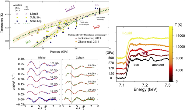
Figure 3. Left top: Fe melting curve determined by x-ray absorption experiments at the Fe K-edge. [78] John Wiley & Sons. Copyright © 2018 WILEY‐VCH Verlag GmbH & Co. KGaA, Weinheim. Left bottom: liquid Ni and Co K-edge experimental spectra and EXAFS fits at different pressures along the melting curve. Reprinted figure with permission from [155], Copyright (2019) by the American Physical Society. Right: single pulse XAS spectra of laser-shocked Fe. Reproduced from [130]. CC BY 4.0.
Download figure:
Standard image High-resolution imageAt the ESRF, iron has been investigated also up to the WDM regime, 500 GPa and 17 000 K, under dynamic solicitation by coupling a portable 35 J laser to time resolved XAS [130]. Single pulse (100 ps long) XAS data have been recorded showing modifications of the XANES and initial EXAFS shape that correspond to solid–solid bcc to hcp phase transition (black and purple lines in figure 3 (right panel), and solid–liquid (melting) transition (red and orange spectra). Interestingly, the persistence of EXAFS oscillation was observed at the most extreme conditions reached, indicating the existence of local ordering in the dense plasma. Moreover a close inspection at the edge region, not shown here, reveals a quite small redshift (0.5 eV) with respect to what predicted by QDM simulations at similar conditions, approximately 2 eV. In general, the K-edge shift indicates a modification of the electronic structure linked to a change in the relative energy difference between the 1s core level and the Fermi level, both affected by temperature and pressure. Such shift under very extreme conditions is not easily predicted by ab-initio theoretical models, mainly due to computational challenges to describe the core level variation, i.e. [154]. What is most notable in this proof of principle experiment is that the XAS data quality for spectra acquired during single bunch experiments is sufficiently good to allow standard EXAFS analysis in solid samples investigations and for a fine comparison to QMD simulations in the liquids.
Using laser-induced dynamic compression to address planetary interiors remains a challenge, because planetary core conditions are typically colder than the typical thermodynamical states achievable by single laser pulse generated dynamic compression, i.e. Hugoniot states. Laser ramp-compression [100] overcomes this problem by shocking multiple times the sample with increasing shock intensities thus limiting the heat flow, and achieving a quasi-isentropic temperature path [33]. Scientists at LCLS used a two stage ramp-compression coupled to XRD to probe the dissociation of hydrogen from carbon (diamond) at 150 GPa and 5000 K in shocked polystyrene (C8H8), simulating conditions of the interior of Neptune and Uranus [62]. However, a disadvantage of this technique are the potential shock wave instabilities caused by large-amplitude pressure waves, and the required laser energy, which for a multistage ramp-compression to several Mbar is too high for the lasers presently installed at large x-ray facilities. An alternative technique is the combination of a laser shock with a sample that is pre-compressed in a DAC. The higher density of the pre-compressed sample with respect to ambient conditions, allows probing material properties at colder states with respect to Hugoniot ones. So far, this technique has been demonstrated only at large laser facilities [15, 16, 34, 75, 76] using moderate pre-compression pressures (within 5 GPa). The initial onset pressure of the pre-compressed sample is extremely important not only as it determines the achievable final pressure and compression path, but also because within the same chemical composition, pressure induced phase transitions can influence the subsequent compression-density curve upon shock. The development of this setup is at present carried out at EuXFEL, and will be available in the next few years for the user community.
3.2. Electronic transitions at extreme conditions
Metallization and spin transitions are among the most common pressure-induced electronic transitions being investigated at x-ray facilities. Metallization occurs when the material develops a solid lattice of ions under compression, while the electrons of the interacting atoms delocalize: instead of orbiting their respective metal atom, electrons move freely throughout the lattice between the atomic nuclei. The most famous example is hydrogen metallization, which is driving the research efforts of an entire community since decades, as outlined in reference [47] and references therein reported. In the years after its first prediction in 1935 by Wigner and Huntingon [140], metallic hydrogen was attributed very fascinating properties such as room temperature superconductivity [5] and superfluidity [6]. Its discovery was described by the Noble Price winner Ginzburg as one of the most important and interesting questions in physics and astrophysics of the century [43], mainly because hydrogen is the most abundant element in the Universe and the main component in production of clean energy via fusion reactions. Recently this year, Loubeyre et al [74] reported synchrotron infrared absorption measurements demonstrating that the amount of infrared light going through a hydrogen sample at 425 GPa is reduced by a factor of around 10−2 compared to lower pressure, suggesting a first order phase transition to metal hydrogen near 425 GPa. Further studies will have to reproduce similar results to finally reach the consensus from the community, but there seems to be a general convergence of results that points to pressures above 400 GPa for metallization to happen i.e. [30, 35, 156]. Hydrogen is only the simplest and lightest element to metallize, but any system, molecular or atomic, exhibits the same behavior at sufficiently high pressures. For example, at ambient temperature the metallization of xenon was determined at 130 GPa [27], while the metallization of krypton is only predicted to occur beyond 400 GPa [111]. Helium, the second most abundant element in the Universe, is predicted to metallize only at P > 10 TPa [146] or 13 g cm−3 at 0 K, but band gap closure might occur at lower densities, ∼1.9 g cm−3, provided the effect of high temperatures (>60 000 K)f is taken into account [16]. The latter results were obtained by optical measurements of reflectivity and temperature by shock-compressed high density (pre-compressed) He in DAC. Clearly, the biggest challenge in the detection of these transitions is to overcome the limits imposed by the experimental setups and diagnostic techniques, thus the development of large scale facilities that provide state-of-the-art experimental and x-ray methods to probe these phenomena at extreme conditions becomes essential.
Electronic transitions have been predicted and observed in many systems at sufficiently high pressures, e.g. [31]. In particular, pressure induced spin transitions in 3d metal compounds are among the most commonly studied because of the ability of 3d metals to exists in multiple valence states, thus forming an incredible number of compounds with different electronic configurations. In a field-free transition-metal ion, the d-electrons are fully degenerate (i.e. the energy of the five d-orbitals is identical). When the ion is placed in a negative electric field, for instance an octahedral field as could be experienced by Fe2+ surrounded by six oxygen anions, the degeneracy of the d-levels is destroyed and the orbitals group into two sets of unequal energy, two higher energies eg and three lower energies t2g orbitals [48]. These are related to the different spatial configurations of the d-orbitals in relation to the octahedral field [42]. This electronic configuration is known as high-spin (HS) state. If the splitting of the levels becomes sufficiently large at high pressures due to the shortening of the bond lengths, the electrons may obtain a sufficient energy from the coupling to overcome the repulsion barrier and may pair, where all 3d electrons are in the lower energy t2g orbitals. This electronic configuration is known as low-spin (LS) state. Pressure-induced spin transitions have been extensively investigated at synchrotrons for Fe-bearing materials of geological relevance [69]. The pairing of Fe 3d electrons causes the collapse of the unit cell, which shrinks, but generally does not lead to a structural phase transition. Low-spin structures have higher densities, affecting properties such as the heat transport and chemical partitioning but also the speed and direction of propagation of seismic waves through the Earth. Spin crossover is also of interest in nanotechnology, where Fe-containing nanomaterials showed potential applications in sensing, actuating, and information processing devices [87]. Studies of spin transitions at synchrotrons have been performed using a wide variety of techniques, from XRD [66, 70, 122] to XAS [17, 59, 118], SMS [18, 64, 87, 122], XES [80, 114] and XRS [137, 138], providing information on the effects of this process at the structural, electronic and nuclear levels. In a recent combined effort between HED scientists and external collaborators (figure 4, caption), a spin transition in FeCO3 was detected at the HED instrument using a combination of XRD and XES techniques, in vacuum at 13 keV photon energy. The setup was installed in IC1 and used a single Si (531) cylindrically bent von Hamos crystal coupled to an ePIX100 detector to measure the Kβ emission line with 0.4 eV spectral resolution. Jungfrau and ePIX100 detectors were placed downstream of the sample to collect simultaneously the XRD signal (figure 4). This experiment benchmarks the possibility to study materials at P above 50 GPa in DACs at XFELs, simultaneously acquiring XES and XRD data, also in combination with high temperatures (>2000 K) generated via x-ray heating (section 3.3.1). In the future, four cylindrically bent Si (531) von Hamos crystals will be available, significantly increasing the detection efficiency and reducing the acquisition times for XES spectra, thus opening up new capabilities for the study of electronic transitions in liquids at high pressures.
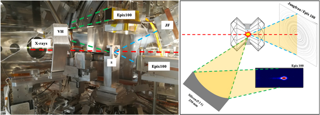
Figure 4. Left: picture of the XES-XRD setup inside IC1. S: sample, VH: von Hamos spectrometer/bend crystal, JF: Jungfrau. Right: graphic representation of the setup. Red dashed lines: incoming x-rays. Green dashed lines: scattered photons from the sample to the von Hamos Si (531) crystal and to the ePIX100 detector. Blue dashed lines: diffracted signal, the position of the detectors was optimized based on the 2θ angles for FeCO3 at 13 keV. Institutes involved in this collaboration are the EuXFEL, University of Dortmund, University of Potsdam, ESRF and ETH-Zurich. A report with the detailed results of the experiment will be published elsewhere. Figure credit: Johannes Kaa.
Download figure:
Standard image High-resolution image3.3. Electron dynamics at extreme conditions
3.3.1. Ultrafast x-ray heating at XFELs
The ultrashort, intense and fully tunable x-ray pulses of an XFEL can excite the electronic system of matter to extreme states. Typical conditions at EuXFEL, i.e. photons of energy 6–10 keV, ∼2 mJ pulse energy delivered in ∼25 fs lead to intensities of the order of 2 × 10¹⁷ W cm−2 when focused to a 5 μm FWHM area. These focused x-ray pulses excite solid-density matter volumetrically, as nonlinear effects are negligible and the photo absorption follows the Lambert–Beer law. However, saturation effects can occur at high intensities [91, 107], which make the energy deposition along the beam more homogeneous. The x-ray pulses excite bound electrons at timescales shorter than a phonon vibrational period, and predominantly couple to certain atomic orbitals when the photon energy is close to atomic resonances or absorption edges [124, 134, 145]. This can be used to excite buried layers or dopants, and higher-Z materials in low-Z containments such as DACs, to electron temperatures exceeding several 100 eV. It is, however, also a potential disturbance to a measurement when intense x-ray are required, e.g. for 'photon hungry' IXS studies, as the intense x-rays excite the electrons and subsequently the ions. In some cases, heating of the sample, or damage and even destruction of the DAC, are undesired side effects.
In a metallic solid, photo-electrons equilibrate with the remaining electronic subsystem into a temperature-like distribution within a few 100 femtoseconds [84]. As the excitation happens faster than any hydrodynamic motion, the ionic lattice at the time of excitation is still cold and the density is constant. Consequently, energy transfer from electrons to ions, which typically occur on picosecond time scales, can only be studied with ultrashort XFEL sources [150].
Another unique possibility at EuXFEL is x-ray excitation of a sample with a MHz burst of subsequent x-ray pulses. Free standing or contained samples (e.g., in DAC) can be sequentially and volumetrically heated and studied with x-ray and optical techniques at the same time. While the minimum delay between two pulses is limited to 222 ns, in the future the HED instrument will also provide x-ray pump–x-ray probe capabilities with delays down to the fs scale, using either a split-and-delay line [79] or a two-pulse mode of the EuXFEL itself.
The x-ray heating of samples in DACs is an interesting alternative to laser heating methods usually adopted to achieve high temperatures at high pressures. The rapid irradiation by the intense hard x-ray pulses generates heating that on the longer timescales (ns, μs) can be considered to be in equilibrium (in terms of electrons and ions temperature). DAC experiments at HED can take advantage of this to reach high temperature states simply by irradiating samples with high repetition x-ray pulses. The volumetric absorption of the x-rays generates much more uniform heating along the x-ray propagation direction as compared to e.g. infrared laser heating. The cooling rates in a typical DAC configuration were calculated to be of the order of few microseconds [85], giving the possibility to simultaneously create and study high temperature states by subsequent x-ray pulses at 2.2 or even 4.5 MHz. Figure 5 illustrates the simulated temperature evolution of a DAC sample subjected to low (0.45 MHz) and high (4.5 MHz) x-ray repetition rates. At x-ray pulse spacing longer than 2 μs (0.45 MHz), the temperature of the sample drops to almost the initial value before the arrival of the next pulse (figure 5, left). At higher repetition rates, however, the pulse train increases the sample temperature in a step-wise manner with the peak temperatures eventually reaching a saturation value after about 10 pulses (figure 5, right). The temperature plateau is given by a balance between the cooling rates and the heat added by the x-ray pulses [85].
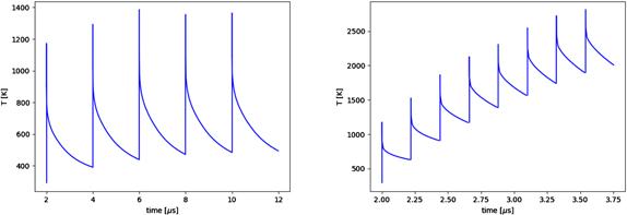
Figure 5. Temporal temperature evolution of a sample in DAC from finite element method analysis. The x-ray spacing is 2 μs (5 pulses) (left) and 222 ns (8 pulses) (right), showing the temperature plateaus towards higher number of pulses. Sufficient temporal distance between subsequent pulses, e.g. 2 μs (left), provide the sample enough time to cool down after each shot. Rapid irradiation by intense hard x-ray pulses, i.e. higher repetition rates (222 ns, right figure) generates heating that on the longer timescales (ns, μs) can be considered to be in equilibrium.
Download figure:
Standard image High-resolution imageFirst DAC experiments at HED in IC1 and IC2 confirmed the predictions about the effect of the pulse trains on heating as a function of the XFEL repetition rate. X-ray diffraction experiments show no thermal shift of peaks due to lattice expansion at 0.45 MHz repetition rates. At 2.2 MHz pulse repetition, however, shifts in all sample diffraction lines towards lower diffraction angles are observed corresponding to the elevated sample temperature (at the moment of the incident x-ray pulse). Additional time-resolved diagnostics is available to measure thermal emission from the heated sample to constrain the temperature evolution during the xfel pulse train. An optical streaked pyrometry system detects the emitted light in the visible spectral range with nanosecond time-resolution. A typical time window used is 5 μs during which thermal response from 10 xfel pulses at 2.2 MHz can be detected (figure 6). At each point of time (in the vertical axis) the spectrum can be fitted to Planck's law to derive the temperature evolution during the pulse train. Additionally to the x-ray heating, the experimental setup features a nanosecond IR pulsed laser for sample heating. Figure 6 demonstrates an example of an experiment where a 300 ns IR pulse arrives ahead of the 10 pulse xfel train. Thermal signal integrated on the time axis shows large thermal response from the laser pulse due to predominantly surface heating and laser spot size being larger than that of the x-ray. After dissipation of the laser pulse energy (cooling time > 1 μs), heating by subsequent x-ray pulses are visible in the step-wise increase of the thermal emission signal. Temperature determination from the time-resolved spectral intensity distribution will be discussed in more detail elsewhere.
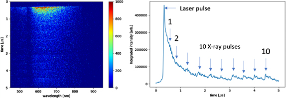
Figure 6. Example of a streak camera image with emission signal from a ns laser pulse and 10 x-ray pulses (left). Intensity projection on the time axis (right).
Download figure:
Standard image High-resolution image3.3.2. Inelastic x-ray scattering and the dielectric function
Matter at extreme conditions may be partially ionized, or exhibit metallic properties. The properties of this subsystem of free and quasi-free electrons define key thermodynamic properties [67], optical properties (refractive index, dielectric function) [22, 123], and transport properties (electrical and thermal conductivity) [142].
Several models exist for the response of the materials electronic subsystem to an external electromagnetic field, the dielectric function, for example the Drude model. Other concepts use the Bohm–Gross approach and yield a semi-classical approximate solution in random phase approximation which does not include collisions [13]. Refinements include quantum mechanical effects [142], electron–ion collisions [128], electron–electron correlations, and quantum degeneracy [40]. The importance of these effects for different areas in the phase diagram of matter at extremes has to be validated by experimental data. Here, a powerful connection exists to inelastic x-ray scattering [44], since the structure factor of the electrons is related to the imaginary part of the inverse dielectric function for collective, longitudinal electron waves, the plasmons.
In order to scatter photons from plasmon waves rather than from individually moving electrons, the scattering lengths needs to exceed the electronic screening length [44]. At the densities of relevance here, this requires photon energies of order 5–10 keV at scattering angles of 5–45°. In this context, an advantage of XFELs with respect to synchrotrons is the higher beam intensity at lower photon energy. This enables to work at lower x-ray energies (down to 5 keV) and larger scattering angles (up to 45 deg), overcoming background scattering and k-vector blurring [147].
The frequency of the longitudinal electron wave (the plasmon resonance), is related to the free electron density. In shock-compressed matter up to a few Mbar, the internal energy gain is typically not sufficient to further pressure-ionize matter. Therefore, the free-electron density ne has a fixed ratio to the atomic density n, and the measurement of the plasmon resonance is a measurement of the density.
Typical values of plasma frequencies of metals at ambient conditions are ∼10–20 eV. In order to resolve the plasmon resonance position to determine the density, an energy resolution better than 10 eV at 5–10 keV is required. At XFELs, this is achieved with hard x-ray self-seeding [2] or monochromators (i.e. Si(111)) which both yield and energy bandwidth ΔE < 1 eV. Note that at XFELs, spectrometers are used to analyze the full IXS spectrum of each exposure in dispersive mode [38, 103, 148], rather than scanning the incident photon energy and having a fixed-energy analyzer, as commonly done in static synchrotron measurements.
In a photon scattering experiment, a redistribution of scattered photons is observed from the elastic peak to inelastic lines due to (de-)excitation of a plasmon. At local thermal equilibrium, the amplitude ratio of these peaks is related to the electron temperature by a Boltzmann factor, the detailed balance relation [44]. This relation provides a model-independent temperature measurement. However, a significant amplitude of the up-shifted plasmon requires electron temperatures of the order of the plasmon shift, which limits this method to high temperatures >10 eV [67].
A first density measurement of shock-compressed matter at an XFEL has been successfully demonstrated in 2015 [39]. In semiconductors and half-metals, the detailed relation of the plasmon shift (at a fixed scattering angle) to compression can reveal influences of band gap closure [151]. If, on the other hand, the plasmon resonance is measured at different scattering angles for a fixed compression condition, the plasmon dispersion is determined. Its shape, in particular at larger momentum transfer exceeding the Fermi wavevector, allows to distinguish the influence of collisional processes and local field corrections at high pressures [104].
In addition to the plasmon shift and amplitude ratio, also its detailed shape can be measured, i.e. the intensity of the inelastically scattered light as a function of energy loss ℏω. This spectrum is in essence the structure factor of the free electrons See which related to the imaginary part of the inverse dielectric function ɛ

where  is the wavenumber, ɛ0 is the electrical susceptibility, ℏ the reduced Planck constant, e the electrons charge, ne the electron density, kB Boltzmann's constant, and Te the electron temperature.
If the measured spectrum extends over a sufficiently large spectral range, the Kramers–Kronig relation can be used to retrieve also the real part of the inverse dielectric function. An example of this approach is shown in figure 7. Here, intense focused 8 keV XFEL pulses from LCLS heat and scatter simultaneously from a thin Al foil. The right panel shows the derived dielectric function for aluminum at extreme conditions. Details of this experiment can be found in reference [123].

Figure 7. Left: measured and calculated inelastic scattering spectrum as a function of the photon energy shift ΔE from aluminum heated by the focused LCLS beam. Fits from three models are shown in comparison. Right: inverse longitudinal dielectric function extracted from the experimental data. The real part is calculated via the Kramers–Kronig relation. For energy shifts below ΔE < 8 eV the plasmon is covered by elastic scattering and could only be extrapolated (blue). Reproduced from [123]. © IOP Publishing Ltd. All rights reserved.
Download figure:
Standard image High-resolution imageIXS measurements can be extended from the free electrons to loosely bound electrons when measuring at higher momentum transfer, where the recoil energy during the scattering is sufficient to ionize bound electrons. Depending on the scattering angle, energy losses of up to several 100 eV allow to measure the position and shape of, e.g., the L-edges in Mg, Al, Si or the K-edge of C.
Finally, it is also possible to perform bound–bound scattering from the electrons that are bound to the atoms. Direct ion temperature measurements via detailed balance using collective scattering from acoustic waves requiring meV spectral resolution have been demonstrated at the LCLS and EuXFEL [25, 82].
Measurements of the detailed shape of the IXS signals have to date only been performed at XFELs with statically or x-ray heated samples, since this photon-hungry technique requires 102 − 103 individual exposures in order to achieve a sufficient signal-to-noise ratio [123]. At EuXFEL, using the DiPOLE laser with up to 10 Hz repetition rate, shock-compression experiments using high-quality IXS will become possible for the first time [149].
At static high pressure conditions, IXS measurements are also routinely performed at synchrotron sources [51, 125]. The small incident x-ray bandwidths and the possibility of using efficient non-dispersive Rowland-circle spectrometers allows precise mapping of the dynamic structure factor S(q, ω), which is directly proportional to the imaginary part of the inverse dielectric function. Plasmon line shapes and dispersions are measured to high precision [71]. An exciting emergent IXS technique, x-ray Raman scattering (XRS) spectroscopy, studies electronic absorption edges of low-Z element containing samples under extreme conditions [116, 117, 121]. At low momentum transfers, S(q, ω) can be shown to be directly proportional to soft x-ray absorption spectra [88]. Much progress has been made in order to expand the reachable pressure range and high-energy-resolution spectra of Si L2,3-edge and O K-edge of glassy SiO2 have been recently measured at pressures exceeding 1 Mbar [96].
3.4. Bridging timescales
Physical and chemical phenomena induced by the application of high pressure and temperature can occur in a range of different time scales (figure 8). Capturing their nature, progress and underlying mechanisms requires therefore adapted acquisitions speeds but also the option to study them in static and dynamic regimes. As can be seen in figure 8 and table A.1 there is a large complementarity of accessible time-scales at synchrotrons and XFELs. The example of the melting curve of MgSiO3 (figure 8, bottom) clearly shows the advantages and disadvantages to study static and dynamic processes. Static studies allow for a fine P/T stepping of experimental conditions to determine the melting line at s to ms time scales [152]. Gas-gun experiments, in turn, 'open the door' to fast processes, i.e. happening at ms–μs intervals and at P/T conditions comparable (or slightly higher) to the static regime, thus permitting to probe e.g. the crystallization process of MgSiO3-bridgmanite (Pv) (figure 8). Laser-shock dynamic compression reveals instead transient states observable on ns time scales and, depending on the characteristics of the laser and experimental setup, might also be capable to extend the accessible P/T experimental conditions. For instance, in the specific case of MgSiO3-bridgmanite, the dynamic compression experimental curve shows a 'cold' compression path that allowed to probe transitory states before crystallization of Ppv (post-perovskite).
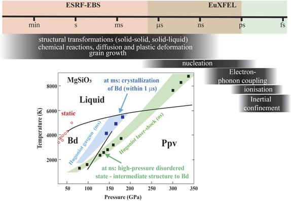
Figure 8. Top: illustration of complementarity between ESRF-EBS and EuXFEL for the study of physical processes at different time-scale, from hrs, min to ps. Bottom: representation that shows the strength and complementarity of each compression technique to establish the phase diagram of MgSiO3. Reproduced from [50]. CC BY 4.0.
Download figure:
Standard image High-resolution imageAnother important aspect is the effect of strain rate (or compression rate) on high-pressure phase transformation mechanisms and kinetics, in particular when kinetics is diffusion-limited. A famous example is given by the case of water. The response of H2O to dynamic processes, such as meteorite or asteroid impacts, is critical to model and predict the state and structure of high pressure ices in planetary bodies in and outside of our Solar System. When large thermodynamic driving forces are applied, local instabilities may lead to different and unforeseen outcomes, such as crystal growth at the crystal-liquid interfaces [61]. Specifically, under dynamic loading, an over-pressure is likely to be applied causing morphological transitions and anomalously fast crystal growth as a function of compression rate. The high strain rate affects not only such macroscopic phenomena but will evidently have an impact on crystalline structure formation as well. Recent laser-driven shock dynamic compression experiments on Si [83] and Bi [46, 95] show discrepancies in the phase transition pressures derived from the static DAC and dynamic shock experiments, thus suggesting that the different strain rates achieved in the two experimental methods play an important role on the structural stability of the materials under investigation. In order to apply the results obtained from dynamic shock experiments to the hydrostatic, low strain rates conditions of planetary interiors, it becomes essential to investigate the effects of high strain rates and shock induced shear on phase transitions [83]. Not only the kinetic properties of the material may shift the P/T boundaries of the stable crystallographic phases but may as well yield new metastable phases. In ice, for instance, a metastable high density amorphous phase forms from ice VI only under rapid compression [20]. Direct probes of the materials' structure during rapid compression are however scarce and so far limited to optical Raman spectroscopy and microphotography techniques.
The difference between the strain rates achieved in static DAC and dynamic compression experiments can be more than 15 orders of magnitude (i.e., from 10−5 s−1 to 1011 s−1). The systematic study of matter under intermediate strain rates (between these two extremes) was not possible until the recent development of the piezo-electric-actuator driven DAC (dynamic DAC, dDAC) technique [37, 55], which enables very precise control of the pressure variation. The dDAC has been shown to achieve compression rates >100 TPa s−1 in Au, i.e. a strain rate of 102 s−1. At 3rd generation synchrotron sources, x-ray flux is the major limitation to deliver quality diffraction information on such short times scales. Results from first experiments on high-Z materials such as Bi (Husband et al, submitted) provide promising insights into kinetic properties at moderate strain rates.
EuXFEL offers an ideal x-ray probe for dDAC applications, by exploiting the pulse structure to follow rapid compression ramps, with a sampling rate of up to 4.5 MHz (a diffraction pattern every 222 ns). The high repetition rate of EuXFEL x-ray pulses is matched to the frame rate of the AGIPD detector [1], capable of collecting diffraction pattern snapshots along the compression ramp over several 100 microseconds. The experimental platform at the HED's IC2 has been designed specifically to enable these moderate strain rate experiments using dDAC technologies and generate high quality diffraction data even from low-Z materials.
3.5. Dynamic response of materials to shock and compression
The response of natural and man-made materials to shock and compression is of crucial importance to understand phenomena such as earthquakes (i.e. fracture of rocks) or failure of engineering devices (i.e. crack propagation in silicon wafers). The combination of polychromatic synchrotron radiation with ultra-high speed image acquisition schemes allows to study such highly aperiodic processes in a single-shot manner: x-ray movies, i.e. series of radiographies acquired continuously at MHz rates that allow to visualize compression waves in granular media and foams or the propagation of cracks in solid media. The use of synchrotron radiation not only gives access to fast acquisition rates: thanks to large source-experiment distance, the (partial) spatial coherent illumination substantially increases sensitivity by means of propagation-based x-ray phase contrast (XPCI). The use of hard x-rays at a long beamline such as ID19 of ESRF gives access to studying macroscopic structures, i.e. with a field-of-view of commonly up to 10 mm × 10 mm. Damage or shock is frequently induced by means of gas guns, shock lasers or explosion [92]. This section illustrates these advantages through selected examples of applications at beamline ID19 of ESRF: cavity collapse induced by impact and shock waves in water induced by wire explosion. Other examples include compression waves in foams as well as crack propagation in a single crystal [93, 105].
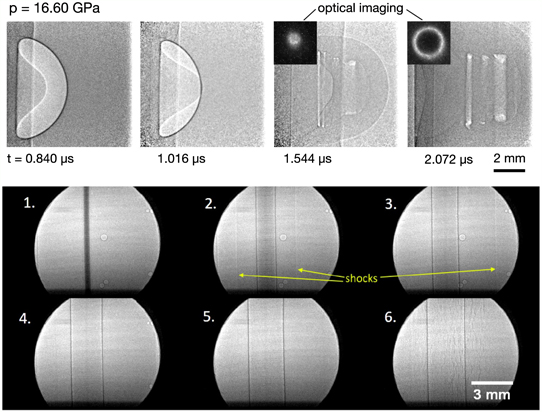
Cavity collapse is a phenomenon of high interest as it can generate strongly localised increases in pressure and temperature. Single-stage and two-stage gas guns can be used to generate impulsively-driven cavity collapse in combination with MHz radioscopy using hard synchrotron radiation. Besides understanding the fundamental processes, cavity collapse studies can also be applied to other fields, such as cleaning of surfaces, shock lithotripsy as well as targeted drug delivery, all of which utilise the localising effects of cavity collapse. Ignition is another important field of application: different mechanisms associated with the collapse of a cavity can substantially lower the ignition threshold. Cavity collapse is currently widely accessible by simulations only, the latter frequently lacking experimental data for verification. The example discussed here provides insight into the collapse process in a solid by impacting cavities in a polymethyl methacrylate medium. Ultra-high speed radioscopy with MHz acquisition rates is used to study cavities impacted to a range of dynamic stress states. Here, single-stage and two-stage gas guns were used, to reach shock pressures ranging from ∼0.5 to 16.6 GPa. The ESRF operated in 16-bunch mode (174 ns bunch separation time). The gas gun is aligned perpendicular to the x-ray beam. The indirect detector deployed consists of two high-speed cameras lens-coupled to the same single-crystal scintillator effectively acquiring images continuously at 3.79 MHz repetition rate (more details on the experimental setup including a sketch are given in the reference) [36]. A selection of acquired images capturing cavity collapse are shown in figure 9 (top), where fluid-dominated dynamics of cavity collapse are probed in the time series of radiographies: the impact is on the left side of the picture, outside of the field of view. The first picture is taken already after the impact, i.e. where part of the cavity is already inverted (left side). In these frames the formation of a jet is also visible, which is an expected phenomenon for strong shock-cavity interactions in a fluid.
Figure 9. Series of radiographs acquired by means of single-bunch imaging. Top: shock-cavity collapse: a 6 mm cavity and 16.6 GPa shock (imaged with 3.79 million images/s acquisition rate). Two insets show the rear-surface images (visible light) of the toroidal plasma emission. Reproduced from [36]. CC BY 4.0. Bottom: a single 200 μm copper wire explosion in water (time delay between frames is 704 ns, 1.4 million images/s acquisition rate). Reprinted from [127], with the permission of AIP Publishing.
Download figure:
Standard image High-resolution image
Shock waves in fluids (water) can also be studied by means of propagation-based phase contrast radioscopy. Wire explosion experiments (such as single wire, two wire or x-pinch) conducted by pulsed power combined with synchrotron-based single-bunch imaging allows for example to image shock propagation in water. For the images shown in figure 9 (bottom) a pulser containing four 50 kV Maxwell pulse capacitors (each capacitance of 220 nF), charged to 32 kV (total stored energy of approximately 450 J) immediately before the experiment, was used to explode a 200 μm copper wire (the pulser had a rise time of approximately 1000 ns). In frame 2 the beginning of the expansion of the wire can be seen. A cylindrical shock wave is launched into the water. The density gradient across the shock front is visible thanks to propagation-based phase contrast. Shock fronts remain visible (partially) in frames 3 and 4, traveling at approximately 2 km s−1. The final frame shows vertical fractures across the image related to cracks appearing in the acrylic sample chamber as a result of the shock. When using a cylindrical arrangement the shock waves generated by electrical explosion can be used to study the merger of shock waves. This can reveal a cylindrical and highly symmetrical shock wave converging on the axis: it is expected to produce a high density, strongly coupled plasma which is ideally suited for WDM research. Images like this provide a direct and quantitative measurement on the formation of the convergent shock wave. Phenomena such as the increased density of water on the axis caused by its arrival as well as its 'bounce' after arrival on the axis can be studied as well. The obtained radiographs can be compared with hydrodynamic simulations, e.g. to reproduce the observed dynamics and to cross-check the agreement with density values [144].
Dynamic compression experiments using gas guns or other means of shock loading such as laser-induced shock, energetic materials, wire explosion or split-Hopkinson pressure bars bridge the time scales between static pressure on one side and XFELs experiments with higher spatio-temporal resolution on the other side. Static experiments under high pressure combined with microtomography include for example research on rock fracture in order to understand the origins of earthquakes [109]. Other examples are static microtomography studies that allow determining density changes across fine P/T intervals to constrain liquid–liquid transitions [49], or studies on the elasticity and viscosity of silicate melts which are key parameters to understand melt migration and volcanic eruptions but which cannot be extracted from dynamic studies [56, 57, 108]. Compared to XFEL-based experiments, high-energy storage rings such as the ESRF give access to higher photon energies as well as larger field of views, for instance frequently required to study sample volumes and materials relevant for engineering applications [132].
Future perspectives for imaging at extreme conditions will be the development of volumetric (3D) MHz tomography at XFELs (see outlook) and the installation of high-flux EBS-beamlines, like the foreseen HPLF-II at ESRF, which will pave the way towards single-bunch imaging outside the classic 16 and 4-bunch timing modes, i.e. GHz image acquisition rates [136]. This will rely on the parallel development of comparably fast diagnostics.
4. Outlook
Large scale facilities offer the unique opportunity to push extreme conditions research to the limit of what is technologically feasible today. In the past decade, user communities from different domains have come together around these facilities to jointly face the challenge of probing new unexplored territories with new, state-of-the-art equipment. Beamline scientists, often assisted and supported by expert users, are developing the most advanced techniques to study matter at extremes. In fact, based also on the necessities of these communities, large scale facilities are now starting upgrade programs to match the most recent technological advancement in terms of accelerators and storage ring physics and engineering. Across the globe, third generation synchrotrons (i.e. PetraIII, APS, Spring-8) are following the example of the ESRF-EBS and will upgrade to a diffraction-limited storage ring. Also, first generation hard XFELs (e.g. LCLS) are upgrading to superconducting accelerator technology, which will increase tremendously the x-ray repetition rate to the MHz regime, as it has been proven at the EuXFEL.
The outstanding performance of these new x-ray sources calls for the development of new methodologies to conduct research at extreme conditions. As we have seen in the chapters above, new experimental techniques are now available, such as x-ray heating at XFELs or XAS/XRD in single-shock dynamic experiments at synchrotrons and XFELs. Also, to fully exploit the potential of the new x-ray capabilities, advances in high pressure generation are necessary and have seen the development of interesting devices, i.e. piezo-driven dDAC, and the currently developed pre-compression DACs for shock experiments (sections 3.1 and 3.4 respectively). Another example and ongoing work is MHz microscopy. X-ray single projection microscopy synchronized to individual pulses at MHz acquisition rates of XFELs offers substantially higher signal level at increased spatio-temporal resolutions compared to storage ring-based light sources e.g. [120, 132]. Combined with recent developments in multi-projection x-ray microscopy, 3D MHz microscopy at XFELs will open new insights into the mechanical properties of materials at high pressures and temperatures at ultra-short time scales [133, 135]. In addition to established techniques to probe atomic and electronic structures, MHz microscopy will depict a materials' change in morphology during, e.g., solid-to-solid and solid-to-liquid phase transitions (project: RÅC IN-VISION and R&D MHz Microscopy). These few examples are only the 'tip of the iceberg' of the numerous research-and-development programs in progress at these facilities, but they clearly evidence their vision and modus operandi.
In conclusion, new generation synchrotrons and XFELs are unique infrastructures that offer a wide range of platforms for research at extreme conditions. The novel possibility to study matter at all timescales from fs to static conditions, encompassing both static and dynamic thermodynamic regimes, is an unprecedented powerful tool to investigate matter at extremes. In the future, answers to yet open research question may become therefore at our reach and new important fundamental advances will be made in our understanding of matter and materials, from WDM and plasmas to superconductors, planetary interiors and novel pressure synthesized chemical compounds.
Acknowledgments
The writing of this manuscript was supported by the European Free Electron Laser- EuXFEL, and the Europen Synchrotron Radiation Facility- ESRF. We greatly thank EuXFEL HED and HIBEF colleagues that participated in the discussion especially but not limited to K. Appel, S. Di Dio Cafiso, T. Feldmann, S. Goede, M. Hassan, H. Hoeppner, R. Husband, H-P. Liermann, J. Mainberger, M. Makita, E-C. Martens, D. Moeller, M. Nakatsutsumi, A. Pelka, C. Prescher, T. R. Preston, M. Roeper, A. Schmidt, J-P. Schwinkendorf, H. Sinn, C. Strohm, K. Sukharnikov, M. Toncian, T. Toncian, T. Tschentscher and P. Vagovic (for MHz tomorography inputs). The authors also warmly thank ESRF colleagues that contributed to the technical details and discussion including O. Mathon, C. J. Sahle, G. Garbarino, M. Mezouar, A. Chumakov, M. Wulff, M. Di Michiel, A. Bosak, W. Crichton, A. Rogalev, F. Wilhelm. The authors acknowledge the European XFEL in Schenefeld, Germany, for provision of X-ray free electron laser beamtime at the Scientifc Instrument HED (High Energy Density Science) and would like to thank the staff for their assistance. The authors are indebted to the HIBEF user consortium for the provision of instrumentation and staff that enabled these experiments. Part of this work was performed with the support of the BMBF project 05K19PE2.
Data availability statement
All data that support the findings of this study are included within the article (and any supplementary files).
Appendix A.
See table A1.
Table A1. Summary of x-ray beam parameters and available setups at ESRF and EuXFEL extreme conditions beamlines a .
| Facility endstation | X-ray diagnostic | HP device | Min. beamsize (μm FWHM) | Energy range (keV) | Max. flux | Max. energy resolution (eV) | Min. acquisition time | Detection system | |
|---|---|---|---|---|---|---|---|---|---|
| ESRF-EBS | ID06 | XRD | LVP | 500 | 17-54 | 1013 s−1 | 1 | ms (XRD) | Pilatus 2M |
| ID09 | XRD, XES | DAC shock (350 mJ laser) | 25 | 5–18 | 109 p−1 | 0.5 | 100 ps (XRD) | CCD Rayonix | |
| ID15a | XRD | DAC | 0.3 | 20–100 | 1013 s−1 | 40 | ms (XRD) | Pilatus3XCdTe | |
| CMOS | |||||||||
| SDD | |||||||||
| ID15b | XRD | DAC (RH, cryo, portable LH) | 7 | 30 | 1013 s−1 | 1 | ms (XRD) | Eiger 9M | |
| ID12 | XAS, XMCD | DAC (cryo) | 2 | 2–15 | 1012 s−1 | 0.3 | 0.5 (XAS) | Si photodiode | |
| SDD | |||||||||
| ID18 | NFS, NIS, SMS | DAC (cryo, LH) | 3 | <100 (NIS) | 1014 s−1 | 10−4 (NIS) | 0.5 h (SMS) | APD | |
| <40 (NFS) | 10−4 (SMS) | ||||||||
| 14.4 (SMS) | |||||||||
| ID19 | HSR, μCT | HP, GG, SHPB, shock (6 J laser) | 103 | 15–150 keV (μCT) | PB: 1016 s−1 | Polychr. | 100 ps (HSR) | Indirect X-ray imaging | |
| 30 keV (BI) | |||||||||
| ID20 | XRS, XES, RXES, RIXS | DAC | 10 | 4–20 | 5 × 10¹³ s−1 | 0.025 | 1 h (XRS) | 72 or 5 CAS | |
| APD Maxipix | |||||||||
| BM23 | XAS, XRF, XES, XRD | DAC (RH, cryo, d) | 3 | 5–40 | 1010 s−1 | 0.4 | 1 min (XAS) | Ionchambers | |
| ID24-DCM | XAS | DAC (LH, RH, cryo, d) | 0.3 | 1013 s−1 | 1 sec (XAS) | SDD | |||
| 5 CAS | |||||||||
| Pilatus 1M | |||||||||
| ID24-HPLF | ED-XAS | Shock (100 J) | 5 | 5–28 | 3 × 10¹⁴ s−1 | 0.5 | 100 ps (XAS) | XH | |
| 104 p−1 | FRELON | ||||||||
| ID27 | XRD, XRF, XAS, μCT | PEP, DAC (RH, cryo, LH) | 0.15 | 15–60 | 1014 s−1 PB: 1016 s−1 | 1 | μs (XRD) | Eiger 9M | |
| PCO Edge, DIMAx, SDD | |||||||||
| ID28 | IXS XRD | DAC (RH) | ∼25 | 17.8–23.7 (IXS) | 1010 s−1 | 10−3 | 20 min | Cd(Zn)Te PILATUS3 1M Si | |
| EuXFEL | IC1 | XRD, XES, IXS | DAC, dDAC, shock (100 J) | <1 | 5–25 | 3 × 10¹⁵ s−1 | 10−4 | fs–min | Jungfrau Epix100 Epix100H |
| X-ray heating | 1012 ph/p | Gottard-II | |||||||
| IC2 | XRD | DAC, dDAC, shock (100 J) | <1 | 5–25 | 3 × 10¹⁵ s−1 | 10−4 | fs–min | VAREX | |
| X-ray heating, pulsed LH | 1012 ph/p | AGIPD | |||||||
aGiven values are corresponding to the main technique at each beamline. Please contact the beamline scientists for more detailed information as the new EBS beamline parameters have not yet been published and no reference can be given at this stage. Abbreviations are as following for each column from left to the right: XES, x-ray emission spectroscopy; NFS, nuclear forward scattering; NIS, nuclear inelastic scattering; SMS, synchrotron moessbauer spectroscopy; HSR = high speed radiography; μCT = micro contrast tomography; XRS, x-ray Raman scattering; RXES, resonant x-ray emission spectroscopy; RIXS, resonant inelastic x-ray scattering; ED-XAS, energy dispersive XAS; IXS, inelastic x-ray scattering; LVP, large volume press; RH = resistively heated DAC; Cryo, cryogenically cooled DAC; LH-laser heated DAC; d = dynamic compression DAC; HP, Hadean press; SHPB = split-Hopkinson pressure bar; GG = gasgun; BI = bunch imaging; PB = pink beam.
Appendix B.
B.1. HPLF-I technical parameters
The laser system consists of two main sub-systems: a front-end amplifier based on an INTREPID amplifier made in continuum (San Jose, USA) and a P-100 amplifier made by Amplitude Technologies (Lisses, FR). The INTREPID delivers up to 15 J at 1053 nm, and will have pulse shaping capabilities from 4 ns to 15 ns and will include the SSD technology (smoothing by spectral dispersion) to control the transverse beam profile at the ESRF target zone. The P-100 amplifier wille get the energy at 1053 nm to the 100 J level using a Nd:glass disk for the amplifying heads. The laser-x-rays delay can be adjusted with 0.25 ns step. Phase plates of different sizes (100, 250 or 500 μm diameter) are foreseen to obtain flat-top focal spot profiles. The laser has a repetition rate up to 1 full-energy shot every 4 min.
B.2. Dynamic compression at ESRF beamlines
A list and description of the beamlines compatible for dynamic compression experiments at ESRF is given below.
ID24-ED provides x-rays in the energy range between 5–28 keV. The beam size at the sample position is ∼2–3 microns at low energies (<10 keV) and up to several tens of microns at high energies. The time resolution is given by the x-ray pulse length, i.e. 100 ps at the ESRF. This is well adapted to laser-shock induced dynamic compression, as the life-time of shocked states lies in the nanosecond range.
Beamline ID09 [143] is optimized for time resolved diffraction and historically dedicated to structural biology. However in recent years dynamic compression experiments have been developed using a 350 mJ laser interfaced to the beamline [14, 95]. While these first studies were limited to moderate pressures of 8–15 GPa, they clearly pointed out the feasibility and potential of coupling laser shock compression to XRD, leading eventually to the HPLF-II proposal.
Beamline ID19 is dedicated to full-field hard x-ray imaging with a strong focus on the use of x-ray phase contrast in combination with microtomography taking advantage of polychromatic photon energy configurations (up to white beam). ID19 is excellently suited to perform ultra-high speed radioscopy up to single-bunch imaging [106]. In special timing modes, defined by the electrons filling pattern in the storage ring, continuous acquisition of images at rates of 1.4 MHz (4-bunch) or 5.6 MHz (16-bunch) allows for recording movies of transient processes propagating up to the speed of sound. With a field of view of up to 10 mm × 10 mm at MHz-acquisition rates, dynamic events can be studied within macroscopic objects. Shock compression can also be routinely coupled to XRI: available installations in the frame of the user program are a single-stage gas gun as well as a split-Hopkinson pressure bar [21, 115]. Laser-shock experiments have been performed with equipment supplied by external groups [93].
B.3. IC1 and IC2 experimental stations at HED instrument
IC1 is rectangular and about (2.3 × 1.4 × 1 m3) in size.
A von Hamos spectrometer for emission spectroscopy (XES) experiments in DAC can be installed inside IC1 and consists of 4 Si(531) crystals with 250 mm radius with 0.3–0.4 eV resolution. The spectrometer is coupled to single-photon counting ePIX [8] and Jungfrau [90] detectors for simultaneous detection of emission lines and diffraction patterns. Possibly in the future, other spectroscopy techniques such as XAS and IXS will be available.
IC2 is round and about 1.4 m in diameter. In IC2, depending on the adopted configuration and the position of the sample stack, the minimum sample detector distance that can be achieved with a 1-megapixel AGIPD detector (frame rate up to 4.5 MHz) [1] will be 150 mm, which results in a coverage up to Q = 9 Å in the vertical at 25 keV photon energy.
The optical system in IC2 for time-resolved temperature measurements consists of a ns laser (SPI lasers, 100 W) operating in pulsed (10–500 ns) and also CW mode, and is employed for double-sided DAC heating in on-axis geometry (co-linear with the x-ray beam). A special feature of this system is an HAMAMATSU streak camera with an S-20 photocathode that guarantees fast acquisitions (ns) of thermal emission spectra from the DAC used for temperature determination via SOP [41].
Both IC1 and IC2 are equipped with high-precision motor stages that allow fine sample alignment with a spatial resolution down to 100 nm.
B.4. The dynamic compression system at HED instrument
The DIPOLE 100-X laser installed at HED instrument can work at 10 Hz and provides pulse shaping capabilities with a resolution of 125 ps to deliver arbitrary temporal pulse shaping between 2 and 15 ns. The laser will be frequency-doubled to 515 nm with expected energies of 70 J at 10 ns pulse length. The laser focal spot at full energy can be as small as 2–3 times the diffraction limit, but for shock generation flat-top focal spot profiles will be obtained through the use of adapted phase plates. The standard configurations provided by the facility are focal spot diameters of 100, 250 or 500 μm diameter.
In IC2, both the DIPOLE and VISAR beam paths can be rotated around the interaction point (sample position) in specific angular positions, allowing different angles between shock propagation and x-ray beam direction. Particularly, a configuration with x-rays and shock propagation nearly co-linear or perpendicular is possible. Inside IC2, in a vacuum compatible air pocket, a VAREX flat panel x-ray detector can be also rotated around the sample position to adapt the angular coverage in diffraction experiments.