


Abstract
Charged particle therapy has been largely driven and influenced by nuclear physics. The increase in energy deposition density along the ion path in the body allows reducing the dose to normal tissues during radiotherapy compared to photons. Clinical results of particle therapy support the physical rationale for this treatment, but the method remains controversial because of the high cost and of the lack of comparative clinical trials proving the benefit compared to x-rays. Research in applied nuclear physics, including nuclear interactions, dosimetry, image guidance, range verification, novel accelerators and beam delivery technologies, can significantly improve the clinical outcome in particle therapy. Measurements of fragmentation cross-sections, including those for the production of positron-emitting fragments, and attenuation curves are needed for tuning Monte Carlo codes, whose use in clinical environments is rapidly increasing thanks to fast calculation methods. Existing cross sections and codes are indeed not very accurate in the energy and target regions of interest for particle therapy. These measurements are especially urgent for new ions to be used in therapy, such as helium. Furthermore, nuclear physics hardware developments are frequently finding applications in ion therapy due to similar requirements concerning sensors and real-time data processing. In this review we will briefly describe the physics bases, and concentrate on the open issues.
Export citation and abstract BibTeX RIS
Corresponding Editor Paul Henri Heenen
1. Introduction
Radiotherapy is an essential component of cancer therapy. The combination of surgery, chemotherapy and radiotherapy is becoming a standard for most cancer patients. Out of the approximately 2/3 of cancer patients receiving radiotherapy, over 80% is irradiated with x-rays produced at linear electron accelerators (Linacs). The others receive specialized treatments such as gamma knife or brachytherapy. Only about 0.8% of the radiotherapy patients are treated with high-energy charged particles, but their number is rapidly increasing (figure 1). The rationale for using accelerated ions in therapy comes from the depth-dose distribution (figure 2), and was originally proposed by Wilson (1946), a student of Ernest Orlando Lawrence at the University of California in Berkeley (CA, USA). The advantages of the Bragg peak shown in figure 2 are quite obvious: unlike x-rays, the energy deposited per unit track increases with depth, therefore for a single beam the dose to the normal tissue will be much lower for ions than for photons when delivering the same dose to the tumor. While in x-ray therapy it is necessary to cross-fire the tumors from many different angles to increase the ratio of the doses to the tumor and normal tissues, only a few beams are necessary if charged particles are used (figure 3). Thus, the same radiation dose to the tumor (and therefore the same tumor control probability, TCP) can be achieved with lower integral dose to the normal tissue (lower normal tissue complication probability, NTCP); or the dose to the tumor can be increased (higher TCP) keeping the same NTCP as expected for x-rays. The most advanced x-ray delivery techniques, such as the intensity modulated radiotherapy (IMRT)5, are almost unbeatable in terms of target coverage, but the cost is an even higher 'dose bath' where the patient is immersed.
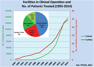
Figure 1. Charged particle therapy facilities in operation and patients treated with charged particles from 1955 to 2014. In the pie chart, the distribution of the patients treated only in 2014 with charged particles in different continents is provided. The total number of patients treated with particles is 137 000, with 15 000 treated in 2014 only. Data from PTCOG website (www.ptcog.ch), charts reproduced with permission from Jermann (2015). CC BY 4.0.
Download figure:
Standard image High-resolution image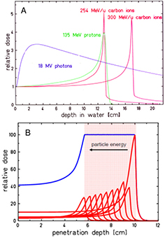
Figure 2. Physical advantages of CPT. (A) Depth-dose distributions of high-energy x-rays and monoenergetic beams of protons or carbon ions. At the same range, C-ions have lower straggling than protons, but a tail of fragments is visible beyond the Bragg peak. In clinical applications, the Bragg peak must be extended to cover all the tumor (B). This can be done by overlapping different pristine beams at different energy and intensity. Figures from GSI Helmholtz Center library, Darmstadt, Germany.
Download figure:
Standard image High-resolution image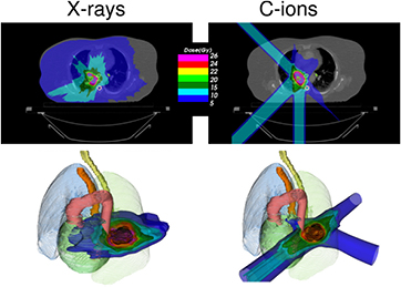
Figure 3. Charged particles produce a reduced integral dose to normal tissue. Treatment of a lung cancer by stereotactic body radiation therapy (left) or carbon ions (right). The plans are designed for a treatment with high-dose single-fraction. Only 3 beams can be used with particles, as also shown in the 3D image below. Plans courtesy of Krjstian Anderle, PhD thesis, Technical University of Darmstadt, Germany.
Download figure:
Standard image High-resolution imageThis simple physics observation begs the question of why so many cancer patients are still treated with x-rays rather than with high-energy ions. Every patient should have a dosimetric benefit from charged particle therapy (CPT) versus x-rays. With its high precision and non-invasiveness, the Bragg peak could be the scalpel of the XXI century. Yet this statement is controversial. In a poll during the August 2012 annual meeting of the American Association of Physicists in Medicine (AAPM), the delegates were asked what they considered the main obstacle for protons to replace x-rays. Almost 20% of the delegates contended that protons would never replace photons. Among the others, roughly half voted for range uncertainty, and the other half for the unproven clinical advantage of lower integral dose. One of the most important aspects in times of increasing health care costs is the cost/benefit ratio of CPT, which leads to strong oppositions to building new centers, heated debates in scientific meetings, and several critical reports in high-impact medical journals (Furlow 2013, Bekelman and Hahn 2014, Martin and D'Amico 2014, Mitin and Zietman 2014, The Lancet Oncology 2014). Here, we will discuss this controversy in light of the recent progress in nuclear physics applied to CPT. Rather than going from physics to medicine after this introductory section, we will instead first show the most recent clinical results, and from there, we will derive the main areas where nuclear physics can contribute to the field.
1.1. Physical basis of particle therapy
The physics of CPT is elegantly described in several books (De Laney and Kooy 2007, Paganetti 2011, Linz 2012, Charlie Ma and Lomax 2013, NuPECC 2014), and review papers in different journals (Lomax 2009, Smith 2009, Belkić 2010, Schardt et al 2010, Bichsel 2013, Newhauser and Zhang 2015), including this same journal (Amaldi and Kraft 2005). We will therefore only briefly describe the physics bases, and concentrate instead on the open issues.
Both the longitudinal and lateral dose profiles (figure 4) resulting from the interaction of charged particles with the human tissues are important in CPT. The longitudinal profile is dominated by the inelastic electromagnetic interaction with atomic electrons, leading to a slow down of the primary particles. Lateral profile is mostly caused by the elastic scattering on target nuclei, and leads to a broadening of the beam. Nuclear interactions reduce the intensity of the primary beam and contribute to both longitudinal and lateral profiles.
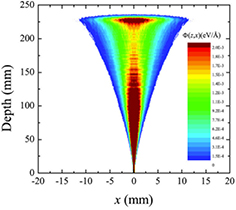
Figure 4. Monte Carlo simulation of the longitudinal and lateral dose spread of a 160 MeV proton beam in water. Φ(z,x) is the dose at depth z and lateral distance x. Figure reprinted from Abril et al (2015), copyright 2015 reproduced with permission from Elsevier.
Download figure:
Standard image High-resolution imageGenerally speaking, these processes (described in section 3) are fairly well understood, even if often not with the accuracy desirable for cancer therapy. The particle range, which is essential for irradiating the tumor, and not the surrounding organs at risk (OAR) in the Bragg peak region, can be calculated by the stopping power. As shown in figure 2(B), the narrow pristine Bragg peak must be extended to cover all the tumor area (spread-out-Bragg-peak, SOBP). This can be done either by passive modulation of the primary beam, or by changing the energy while raster scanning tumor slices with a pencil beam (figure 5). Scanning provides superior dose distributions compared to passive modulation, and greatly reduces the production of secondary neutrons, which may represent a risk for secondary cancers (see section 4.4). However, the interplay between pencil beam scanning and organ movement (figure 6) caused by breathing jeopardizes the dose distribution, and makes treatment of moving targets—e.g. lung tumors—with spot scanning much more complicated than with passive modulation (Bert and Durante 2011). The range uncertainty, due to organ movements and other causes (see section 5), requires to deliberately deliver a higher range as prescribed in order to avoid missing part of the tumor. This in turn can move the SOBP into an OAR, thus increasing toxicity. Lateral scattering broadens the beam and creates an undesired penumbra. Figure 7 shows that the penumbra is reduced by increasing the atomic mass of the ion used in therapy (see section 3.2). Nuclear interactions generate slow target fragments, which give a small contribution to the dose but can have high biological effectiveness. If particles heavier than protons are used, projectile fragmentation produces fast fragments with a mean velocity similar to the velocity of the primary ion. These fragments have lower mass and therefore higher range than the primary ions (see section 3.1), thus generating a longitudinal tail in the Bragg curve (figure 2). The angular distribution of the fragments is narrow in the forward direction, but the spread of the lighter fragments (protons and helium) contributes to the lateral widening of the beam.
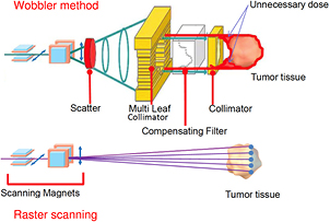
Figure 5. Passive and active charged particle beam delivery systems. Pencil beam scanning has several advantages compared to passive scattering including (1) high beam efficiency; (2) uniform coverage of complexly-shaped tumors; (3) daily adaptive planning; (4) no extra dose in the proximal region; (5) no need for bolus and multi-leaf collimators; (6) reduced neutron production. One problem with scanning is the management of moving organs (see figure 6). Image courtesy of Toshiba, Japan.
Download figure:
Standard image High-resolution image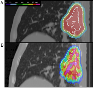
Figure 6. The interplay between pencil beam scanning and organ motion jeopardizes the dose distribution. (A) A lung tumor treated with beam scanning assuming no motion. A uniform dose is delivered to the clinical (CTV) and planning (PTV) target volumes. (B) the actual dose distribution caused by patient's breathing. Image courtesy of Prof Christoph Bert, University of Erlangen, Germany.
Download figure:
Standard image High-resolution image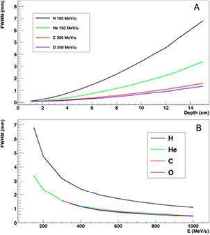
Figure 7. Lateral spread of different ions in water. Calculations were done using the Monte Carlo Code Geant4, and the y-axis shows the standard deviation of the Gaussian fit of the beam spot distribution. (A) Calculation as a function of the depth for beams of different energy, having the same range of 15 cm in water. (B) Calculation as a function of the energy of different beams after traversing 15 cm in water.
Download figure:
Standard image High-resolution imageHirohiko Tsuji and other Japanese radiotherapists elected to use C-ions and started a program at the National Institute for Radiological Sciences (NIRS) in Chiba in 1994, with more than 8000 thousand patients treated to date for almost all kind of solid tumors in different regions (Tsujii et al 2014, Kamada et al 2015). The NIRS success led to a widespread use of carbon therapy in other heavy ion facilities in Asia and Europe. The USA is also planning a C-ion therapy facility in the near future, over 20 years after the termination of the clinical trial at the Lawrence Berkeley National Laboratory. However, other ions with 1 < Z < 6 (especially 4He) or slightly heavier than 12C (e.g. 16O) can play a role in CPT (see section 3.4).
1.2. Ion radiobiology
In addition to the physical advantages, CPT can exploit several biological advantages. Cell survival S after exposure to ionizing radiation is generally approximated at therapeutic doses with a linear-quadratic function

where D is the dose in gray (Gy) and the α/β ratio defines the radiosensitivity of the tissues. Tumors and early, acute reactions in the normal tissue have generally high α/β ratio (around 10 Gy), while late normal tissue complications, the main limit for the total dose in radiotherapy, normally have low α/β ratio (around 2 Gy). This differential radiosensitivity is the base for fractionation in radiotherapy, because split doses will spare normal tissues (low α/β ratio) more than tumors (high α/β ratio).
Cell survival studies showed already many years ago (Blakely et al 1984) that heavy charged particles have an increased relative biological effectiveness (RBE) compared to x-rays, mostly described by an increase in the α parameter, resulting in steeper survival curves. The RBE is defined as the ratio Dx/Dp of the x-ray and particle radiation doses giving the same biological effective—e.g. 10% cell survival (RBE10). The RBE depends on several physical (LET6, dose, dose rate, fractionation, particle mass etc) and biological (intrinsic radiosensitivity, biological endpoint, oxygen concentration, cell cycle phase, proliferation rate, etc) parameters (Durante and Loeffler 2010). Data mining of RBE values (Friedrich et al 2013) from cellular experiments performed in the past 50 years with different ions always shows a large variance (figure 8). The general trend is always the same: an increase from low-LET up to 100–200 keV μm−1, and then a decrease at very high-LET caused by the overkilling effect. Light particles are generally more effective than heavy particles at the same LET, because they are slower and therefore have a narrow track width. The biological advantages of irradiating a tumor with a high-LET ion goes beyond the RBE for cell killing: the oxygen enhancement ratio (OER), cell-cycle variation in sensitivity, and sparing by fractionation are reduced with densely ionizing radiation, making CPT ideal against hypoxic tumors, or with many proliferating cells. More evidence is also accumulating showing that high-LET radiation has distinct radiobiological effects compared to low-LET, e.g. reducing angiogenesis and cell migration (Loeffler and Durante 2013). Taken together, these data suggest that using a charged particle with low-LET in the entrance channel (high velocity) but of relatively high-LET in the SOBP (low velocity) will provide a further biological improvement to the treatment beyond the physical advantages.
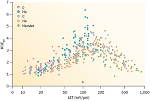
Figure 8. RBE compared with LET from published experiments on in vitro cell lines. RBE is calculated at 10% survival, LET values are given is keV μm−1 in water. Different colours indicate different ions, from protons to heavy ions. Data points are extracted from the particle radiation data ensemble (PIDE) database (Friedrich et al 2013), which currently includes 855 survival curves for cells exposed to photons (α/β ratio ranging 1–30) and ions. PIDE is available online at www.gsi.de/bio-pide. Figure from Loeffler and Durante (2013), copyright 2013 reproduced with permission from the Nature Publishing Group.
Download figure:
Standard image High-resolution imageProtons used in therapy generally have an entrance energy between 150 and 250 MeV (15–35 cm range in water), corresponding to a low-LET in water around 1 keV μm−1. The LET on the SOBP increases with depth in a range of 2–6 keV μm−1 (Paganetti 2014). It is expected that this modest LET increase will correspond to an increased RBE (figure 9), using the data from the same PIDE database shown in figure 8 (Tommasino and Durante 2015). However, the effect is arguably significant only in the last few mm of the SOBP. Thus, the proton therapy community has adopted a constant RBE of 1.1, which seems to be reasonable considering the unavoidable spread associated to RBE estimates (Paganetti 2002). A significant increase in RBE, and other special high-LET radiation effects, in the SOBP-tumor volume can only be achieved using heavier ions, where the LET reaches the maximum value in figure 8. For this very reason, Cornelius A. Tobias proposed using different heavy ions during the clinical trial at the Lawrence Berkeley Laboratory 1975–1992: He, Ne, N, O, C, Si, and Ar (Castro 1995). The use of very heavy ions, such as argon, was justified by the goal of overcoming hypoxia, which requires very high-LET according to the cell experiments performed at the Bevalac accelerator in Blakely et al (1984). However, the entrance LET for this very heavy ions is already quite high, and an increased NTCP was observed. Carbon represents a good compromise, with an LET in the entrance channel between 11 and 13 keV μm−1, and a fairly high LET on the SOBP between 40 and 90 keV μm−1.
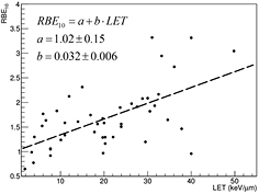
Figure 9. RBE values for 10% survival for protons as extracted from PIDE (see figure 8). The dashed line shows the tendency to an increase in RBE with LET and is the result of a linear fit. Figure from Tommasino and Durante (2015), reproduced with permission. CC BY 4.0.
Download figure:
Standard image High-resolution imageThe increased biological effectiveness is a great advantage of CPT compared to x-rays, but unfortunately it is often regarded as a problem, because of the high uncertainty in the RBE (figure 8). In proton therapy, the RBE of 1.1 is generally acknowledged as a practical, yet incorrect approximation, potentially leading to a bias in the treatment planning if not considered in the optimization (Paganetti 2014). The topic is very much debated and many papers are published with simulations and models (e.g. Giantsoudi et al 2013, Grün et al 2013, Sethi et al 2014a, Wedenberg and Toma-Dasu 2014, Guan et al 2015, Jones 2015, Polster et al 2015), yet the implementation of an RBE model in a clinical treatment plan has never been tried. The question remains whether the clear experimental evidence pointing to a variable RBE, different from 1.1, is really clinically relevant.
Because proton therapy plans are not optimized in RBE-weighted dose, expressed in Gy(RBE)7, biology is considered independently from the physics driven planning process using the RBE = 1.1 approximation and considering uncertainties. In C-ion therapy, instead, plans are optimized using the Gy(RBE). Essentially two different models are used for the calculation of the Gy(RBE): the Japanese centers use a model developed at NIRS, where the shape of the SOBP is based on in vitro cell killing experiments. The curve is then normalized using a region in the SOBP which is isoeffective to neutrons, whose clinical RBE was determined as 3 from previous clinical experience in Japan (Matsufuji et al 2007). On the other hand, the GSI Helmholtz Center in Darmstadt (Germany) developed a specific biophysical model (local effect model, or LEM), which predicts the RBE for different ions and tumor types starting from the corresponding clinical photon data and an amorphous track structure model (Krämer and Scholz 2000). Amorphous track structure models use average dose distributions along the track of the heavy ions, assuming that the dose decreases as r−2, where r is the track radius. Once the physical dose distribution is described, the biological response can be derived from x-ray survival curve, and the model can predict the effect of any ion. Already introduced by Bob Katz in the 60s (Butts and Katz 1967), these models are sometimes criticized by supporters of micro- or nano-dosimetry because they do not account for the high heterogeneity of the dose distribution at the nm level, already visible with x-rays (Beuve 2009). However, recent measurements of DNA damage distribution in vivo show that the predicted radial dose distribution corresponds to an observed biological damage distribution (Mirsch et al 2015). Amorphous track structure approximations remain therefore a simple and valid tool for prediction of charged particle effects starting from x-ray radiosensitivity. The LEM is able to reproduce the RBE of light and heavy ions for inactivation of cells with different intrinsic radiosensitivity, and has been improved many times in the past years (Grün et al 2012). It is currently being used in the C-ion therapy centers in Germany (Heidelberg and Marburg), Italy (Pavia), and China (Shanghai). An experimental intercomparison between NIRS and GSI using in vitro cells and mice provided comparable results, in agreement with the measured RBE (Uzawa et al 2009). However, the two models give different predictions of the Gy(RBE) when different fractionation schemes and tissue radiosensitivity are compared (Fossati et al 2012; Steinsträter et al 2012). In order to make use of the full potential of carbon beam scanning, NIRS has recently introduced a modified microdosimetric kinetic model (MKM) that can adapt optimization procedures to various biological parameters (Inaniwa et al 2015). This is particularly important for hypofractionation regimens, where the use of a dose-dependent RBE is necessary to take into account the reduced RBE at high dose/fraction (Friedrich et al 2014).
The International Commission on Radiological Units (ICRU), in collaboration with the International Atomic Energy Agency (IAEA), is currently working on the definition of the correct unit for the isoeffective dose, and this activity is generally considered as highly relevant for the intercomparison of the prescribed clinical doses. If the RBE model is correct, n Gy(RBE) should result in the same TCP as n Gy in x-ray therapy. However, claiming that the RBE uncertainty is a showstopper for the clinical use of C-ions, and is a major hindrance to the introduction of new ions in therapy, is not justified by the excellent clinical results gathered in Asia and Europe with heavy ions without significant side effects (see section 2.3). In Lanzhou (China), patients are treated for superficial and deep tumors with carbon ions without any correction for RBE, that is, using a flat SOBP in physical dose (Li and Sihver 2011), similar to the flat RBE in proton therapy. This obviously results in large overshoots in the distal tumor region and structures downstream, but apparently this is acceptable. Overdosages, in fact, are becoming quite common in x-ray therapy, especially in stereotactic radiosurgery (SRS) or stereotactic body radiotherapy (SBRT).
Beyond the tumor RBE, research should focus on the new emerging radiobiology which may open new scenarios in CPT and provide novel biology-guided applications in the clinics: examples are the sensitivity of cancer stem cells, hypoxia, genetic background, angiogenesis and vascular damage, combination of particles and drugs (chemotherapy or immunotherapy) etc (Durante 2014a). Thus, instead of correcting for RBE effects, we will in the future utilize RBE variations to our advantage. In addition, much more research should be dedicated to the RBE for normal tissue effects. If overdosages are acceptable in the tumor, they can lead to severe toxicity in the normal tissue, and it is therefore the RBE in the normal tissue that should limit the possible dose escalation in CPT. Radiobiology of normal tissue is complex because cell survival experiments are hardly relevant for endpoints such as fibrosis, cardiomyopathy, cognitive deficits or second carcinogenesis. While plenty of studies concentrated on tumor control, only a few animal experiments have measured RBE of C-ions in normal tissues, comparing the results with RBE models (Ando et al 2005; Saager et al 2015, Sørensen et al 2015). More experiments are urgently needed for a safe dose escalation in CPT.
1.3. Status of particle therapy facilities
As a consequence of the expected advantages of CPT, the number of clinical centers is steadily increasing. The number of patients treated is given in figure 1. Out of about 137 000 patients treated worldwide with CPT, 87% were treated with protons, 11% with C-ions, and less than 2% with other ions (Jermann 2015). The rapid growth rate is remarkable, with countries such as Great Britain and The Netherlands planning already for 3–4 centers, starting from zero. This is partly due to the reduction of the costs. The capital cost for CPT facilities is still relatively high compared to photon therapy, and is dominated by construction and technology component costs. Until a few years ago, at a start-up cost of approximately $150 million, it was difficult for institutions to finance a full-scale CTP endeavor alone, with a significant focus placed on private sources of capital, as well as on bank loans and bond financing. These days, however, the costs are drastically dropping especially for 'small-scale' (compact proton cyclotron, single room) centers. A hospital already having a bunker for the accelerator can currently buy a single-room gantry proton therapy center for approximately $20 million. In a single-room facility, the number of patients per year will be limited compared to a large-scale facility, where the investment cost can be compensated by relatively high reimbursement. However, the trend toward a cost reduction seems to be very significant. Estimates of cost per fraction published a few years ago (Peeters et al 2010) ranged 578–1300 € for a proton therapy facility compared to 190–407 € for an x-ray clinics, but these costs are also rapidly dropping. The capital and running costs are higher for multiple ion facility: about 50% higher than for a proton-only center. However, the costs per quality-adjusted-life-year (QALY) can lead to surprising results. For example, in the Japanese system, C-ion therapy is cost-effective for patients with locally recurrent rectal cancer (Mobaraki et al 2010).
Apart from the cost, the question is how many centers are needed to treat patients that can potentially benefit from CPT. This obviously depends on the clinical results, and as shown in table 1, different countries have different lists of pathologies eligible for CPT. While the established indications, where the advantage of particles is without doubts (e.g. ocular tumors and skull base chordomas), cover 1–2% only of the cancer patients, including clinical trials this fraction reaches 15–20% and can potentially be higher. The Italian Association for Radiation Oncology (AIRO) made an estimate almost 10 years ago based on elective pathologies (e.g. ocular melanoma) and clinical trials (Krengli and Orecchia 2004). They estimated 120 000 new radiotherapy patients per year in Italy, 1885 definitely eligible for proton therapy and about 15 000 and 7000 to be enrolled in clinical trials with protons or heavy ions, respectively. Based on this estimate, AIRO recommended 1–2 centers for heavy ions and 4–5 centers for protons. Currently, Italy has one center for heavy ions, one for deep seated tumor protontherapy and one for low-energy protontherapy (eye tumors). The Dutch are instead using a model-based approach consisting of two phases: the first aiming at the selection of patients who may benefit from protons, and the second at the clinical validation by sequential prospective observational cohort studies (Langendijk et al 2013). The patients are selected using an NTCP model inside an in silico clinical trial. Only patients with an estimated % reduction of the NTCP-value beyond a threshold are selected for protontherapy. The toxicity results obtained in these patients will be compared to those obtained in the historical control group. The model-based approach is complicated, but science-based and intrinsically prone to control and corrections. These selection models for patients should be encouraged and used in planning the number of CPT facilities needed.
Table 1. Recommended indications for CPT in different countries.
| Country | Document | Group 1 (medically necessary) | Group 2 (potential indications) |
|---|---|---|---|
| USA | ASTRO |
▪ Eye tumors | All other solid tumors, including: |
| ▪ Head and neck cancers | |||
| ▪ Chordoma and chondrosarcoma | ▪ Thoracic malignancies | ||
| ▪ Spine tumors |
▪ Abdominal cancers | ||
| ▪ Hepatocellular carcinoma |
▪ Pelvic cancers | ||
| ▪ Pediatric tumors |
|||
| ▪ Patients with genetic syndromes |
|||
| UK | Clinical indications for treatment overseas by protons | ▪ Skull-base and spinal chordoma | |
| ▪ Skull-base chondrosarcoma | |||
| ▪ Spine and paraspinal soft-tissue sarcomas |
|||
| ▪ Pediatric tumors | |||
| Italy | AIRO |
▪ Skull base and spine chordomas and chondrosarcomas |
|
| ▪ Adenoid cystic carcinoma of the salivary glands |
|||
| ▪ Mucosal malignant melanoma |
|||
| ▪ Ocular melanoma | |||
| ▪ Osteosarcomas |
|||
| ▪ Pediatric tumors | |||
| Denmark | Aarhus University, Indications for the Danish National Center for Particle Therapy | ▪ Chordoma and chondrosarcoma | |
| ▪ Ependymoma | |||
| ▪ Primitive neuroectodermal tumors | |||
| ▪ Pituitary adenoma | |||
| ▪ Acoustic neuroma | |||
| ▪ Arterovenous malformations | |||
| ▪ Germinoma | |||
| ▪ Eye tumors | |||
| ▪ Lymphomas | |||
| ▪ Selected sarcomas | |||
| ▪ Nasopharyngeal cancer recurrence | |||
| ▪ Pediatric tumors | |||
| The Netherlands | Health Council of the Netherlands on Proton Therapy |
▪ Skull base and spine chordomas and chondrosarcomas | ▪ Re-irradiations |
| ▪ Paranasal sinus tumors | |||
| ▪ Meningioma | ▪ Nasopharyngeal carcinoma | ||
| ▪ Pediatric tumors | ▪ Retroperitoneal sarcoma | ||
| Canada | AHS |
▪ Chordomas and chondrosarcomas | ▪ Benign tumors of the CNS |
| ▪ Ocular melanomas |
▪ Paranasal sinus and nasal cavity tumors | ||
| ▪ Pediatric tumors | |||
aAmerican Society for Therapeutic Radiation Oncology, 2013. bWhen the spinal cord tolerance may be exceeded, or for re-irradiation. cIn hypofractionated schedules. dWhen the treatment plan shows decreased normal tissue dose and therefore lower toxicity is expected. eRadiosensitive syndromes such as retinoblastoma or NF-1. fNon-Ewing. gItalian Association for Radiation Oncology, 2015. Includes protons and C-ions. hUnresectable or with post-surgery residual disease in critical volumes. iAn evidence-based model based on NTCP has been then accepted in The Netherlands (see figure 10). jAlberta Health Services, 2014. kNot suitable for plaque brachytherapy.
2. Clinical results
2.1. Clinical indications
Tumor indications for CPT are generally those close to OAR, where a steep dose gradient is necessary. Typical cases are chordomas and chondrosarcomas of the base of the skull and eye tumors. Other indications are those patients where the reduction of the normal tissue dose is essential: children treated with curative intent and patients with genetic, radiosensitive syndromes. In addition, re-irradiations are often referred to CPT, especially for tumors of the spine where spinal cord tolerance can be exceeded using x-rays. For C-ions, radioresistant tumors such as inoperable osteosarcomas and mucosal malignant melanoma are also included. This group is relatively small, but is generally acknowledged as the cohort where CPT is medically necessary. In principle, though, the cohort of patients eligible for CPT is much larger, and it includes the most common malignancies (lung, prostate, breast) and those with high mortality (pancreas, glioblastoma, local recurrence of rectal cancer). In table 1, we compare the model policy recently proposed by the American Society for Radiation Oncology ASTRO (2014) to the recommended indications in other countries.
ASTRO indicates very few cases where use of CPT is not supported, i.e. those of clinical urgency, extensively moving organs, or palliative treatments where x-rays would not exceed the organ tolerance dose. In the following paragraphs, we will concentrate on the tumors that ASTRO includes in the group 2, i.e. those suitable for coverage-with-evidence. Most of the controversy related to CPT is due to the lack of phase III comparative clinical trials8. The importance of randomized, prospective trials is generally acknowledged in the radiotherapy community (Allen et al 2012, Combs and Debus 2013). Retrospective trials, relying on observational data, are very controversial. For prostate cancer, retrospective comparisons failed to detect any improvement of protons versus x-rays (Sheets et al 2012, Yu et al 2013) but those studies could not compare the treatments at the same parameter (total dose, fractionation, dose-volume histograms) level (Mendenhall et al 2012). Prospective randomized trials should focus on areas where clinical equipoise is present, tumor sites where there is a low risk of systemic failure, a high risk of local progression and/or a high risk of toxicity with conventional therapy (Miller et al 2013). However, it should be underlined that conducting proper clinical trials is expensive and the data on late-effects require substantial follow-up time. In some cases, especially for pediatric patients, a randomized trial of photons versus protons would be unethical (Suit et al 2008). Comparative trials are also complicated by the many variables to be considered: dose distribution, total dose, fractionation schedule, adjuvant systemic therapy, LET spectrum, ion species (Loeffler and Durante 2013). It is difficult to interpret trials where only one factor is directly compared.
Notwithstanding these problems, several phase I/II trials have been completed and a few phase III trials are ongoing (table 2). Several reviews of the clinical results have been published (Terasawa et al 2009, De Ruysscher et al 2012) and we will only summarize the most recent results below.
Table 2. Ongoing phase-III randomized clinical trials comparing different radiation qualities (protons, C-ions, x-rays) for the same disease.
| Brief title | Sponsor | Start date | Condition | Arm 1 | Arm 2 |
|---|---|---|---|---|---|
| IMPT |
MDACC |
August 2013 | Oropharyngeal cancer | Protons |
X-rays |
| Proton therapy versus IMRT |
MGH |
July 2012 | Low or intermediate risk prostate cancer | Protons | X-rays |
| Proton beam therapy versus IMRT |
MDACC |
April 2012 | Esophageal cancer | Protons |
X-rays |
| Comparing photon therapy to proton therapy to treat patients with lung cancer | RTOG |
February 2014 | Stage II-III NSCLC |
Protons |
X-rays |
| Pragmatic randomized trial of proton versus photon therapy for breast cancer | PTCORI |
2015 | Post-mastectomy stage II or III breast cancer | Protons | X-rays |
| Trial of proton versus carbon ion radiation therapy in patients with chondrosarcoma | Heidelberg University, Germany | August 2010 | Low and inter-mediate grade chondrosarcoma of the skull base | Protons | C-ions |
| Randomised trial of proton versus carbon ion radiation therapy in patients with chordoma | Heidelberg University, Germany | July 2010 | Chordoma of the skull base | Protons | C-ions |
| First French prospective randomised study of the medical and financial potential of carbon ion therapy | Lyon University Hospitals | 2016 | Adenoid cystic carcinoma and sarcomas | C-ions | IMRT |
| Prospective trial comparing carbon ions to IMRT |
NCI |
2016 | Locally advanced pancreatic adenocarcinoma | C-ions |
X-rays |
Note: Phase I/II studies and phase III studies comparing different fractionation schedules with protons, or the combination of particles and chemotherapy, or a comparison with other non-radiotherapy methods are not included. aIntensity modulated proton therapy. bIntensity modulated radiation therapy (x-rays). cMD Anderson Cancer Center, Houston, TX, USA. dCombined with chemotherapy. eMassachusetts General Hospital, Boston, MA, USA. fRadiation Therapy Oncology Group. gNon-small cell lung cancer. hPatient-Centered Outcomes Research Institute. iNational Cancer Institute.
2.2. Proton clinical trials
As shown in table 1, there is a general consensus on the effectiveness of protons for tumors of the eye, base of the skull, and spine. Patients with nasal cavity and paranasal sinus malignant diseases also have better outcome when treated with protons rather than with IMRT (Patel et al 2014).
Pediatric patients are traditionally considered a main motivation for proton therapy. About 10% of the patients treated with protons in 2014 were pediatric (Jermann 2015). Dosimetric studies of proton radiotherapy compared with best available photon based treatment show significant dose sparing to developing normal tissues (Armoogum and Thorp 2015). Clinical data are now emerging that begin to quantify the benefit in decreased late treatment effects while maintaining excellent cancer control rates. A prospective study on health-related quality of life at the Massachusetts General Hospital in Boston shows that pediatric brain tumor survivors treated with protons compare favorably to those treated with x-rays and similar to healthy controls (Yock et al 2014). One major concern about late effects in pediatric patients is the induction of second malignant neoplasms. Owing to the reduced exposure of the normal tissues, protons are expected to reduce the risk compared to photons (Xu et al 2008, Newhauser and Durante 2011). Concern has been raised about the possible role of neutrons in the induction of second cancers (Brenner and Hall 2008), a problem relevant for both high-energy x-ray therapy (>8–10 MV, threshold for photoneutron production) and CPT. However, neutron production is drastically reduced using raster scanning, where the beam energy is changed actively rather than using passive modulators. As a result, the distal dose is much lower with protons or C-ions delivered by scanning than with CPT in passive modulation or 25 MV x-rays (La Tessa et al 2012). In line with the predictions of the model calculations, the first epidemiological studies from the Massachusetts General Hospital show that the incidence of second malignancies in patients treated during childhood with protons is lower than for x-rays (Chung et al 2013, Sethi et al 2014).
Beyond the clinical indications above, the main question is whether protontherapy is cost-effective for tumors with high prevalence: prostate, lung, breast, and gastrointestinal cancers.
Prostate is the most common cancer treated with protons, accounting for 2 of every 3 claims and 80% of Medicare spending on the procedure in USA. Despite the expected benefit in terms of reduced morbidity for the rectum and the bladder, the lack of solid evidence streamed a very heated controversy (Martin and D'Amico 2014, Mitin and Zietman 2014, The Lancet Oncology 2014). Retrospective comparisons did not show any advantage in using protons, and considering that the cost of the therapy is almost two times higher (Medicare reimburses approximately 32 000 $ for a proton treatment and 19 000$ for a x-ray treatment of prostate patients) this has caused a lot of criticism against proton therapy in general. An ongoing randomized prospective trials at MGH in Boston (table 2) should clarify whether protons are useful for low and intermediate risk prostate cancer.
Lung cancer is the leading cancer-related cause of death in males both in US (Siegel et al 2015) and Europe (Malvezzi et al 2015). A randomized trial is also ongoing for stage II and III non small cell lung cancer (NSCLC) (table 2). The current results, often difficult to compare, show similar tumor control with SBRT and CPT (Wink et al 2014, Berman et al 2015). The question is whether CPT may provide lower NTCP in hypofractionation regimes, as in silico studies suggest (Zhang et al 2010, Roelofs et al 2012).
Breast cancer has the highest incidence among women in the USA (Siegel et al 2015) and Europe (Malvezzi et al 2015). Patients receive usually surgery first, followed by radiotherapy, which generates concern for normal tissue toxicity. Because protons stop in tissue, it is possible to almost completely spare the heart. The lung dose is also greatly reduced. Recent epidemiological evidence shows that women treated for left sided breast cancer with radiotherapy are at high risk of late cardiac toxicity, and the risk increases linearly with the mean heart dose (Darby et al 2013). Proton therapy gives a substantial reduction of the dose to the heart, left anterior descending artery and lung, even for patients treated with deep inspiration breath hold (Lin et al 2015). Early results of ongoing phase I/II trials in postmastectomy breast cancer patients show that the treatment is effective, well tolerated, and gives high ipsilateral breast progression-free survival with excellent cosmetic results (Chang et al 2013, MacDonald et al 2013, Bush et al 2014, Cuaron et al 2015). However, the target lumpectomy cavity is difficult to visualize and can move (Strom and Ovalle 2014). In addition, the target is shallow and therefore skin toxicity can limit beam arrangement and prescription doses (Whaley et al 2013, Galland-Girodet et al 2014)
Gastrointestinal cancer patients are also increasingly treated with protons. ASTRO (table 1) acknowledged that protons are superior to x-rays for the treatment of hepatocellular carcinoma in hypofractionation, as demonstrated by the results from Tsukuba (Mizumoto et al 2012) and Loma Linda (Bush et al 2011). Liver is therefore becoming a new elective target for protontherapy (Dionisi and Ben-Josef 2014) and could be a candidate for a phase III trial. Survival rates with SBRT are comparable to CPT, even if the acute and late toxicities are higher (Qi et al 2015). This suggests that there can be a potential for further hypofractionation in CPT for liver cancer, going below the 10 fractions currently used toward the 3 fractions used in SBRT (Durante 2015). Esophageal cancer has a very poor prognosis and is currently the 7th leading cause of death among US men (Siegel et al 2015). Chemoradiation treatment of esophageal cancer patients gave very good results using protons (Lin et al 2012, Ishikawa et al 2015). A phase III clinical trial comparing protons to IMRT is currently ongoing at the MD Anderson Cancer Center in Houston (table 2). Pancreatic cancer, usually ductal adenocarcinoma, is the 4th cause of cancer-related death in USA (Siegel et al 2015) and the only cancer for which deaths are predicted to increase in Europe for both men and women in 2015 (Malvezzi et al 2015). Even after surgery, mortality remains very high. Radiotherapy is used for radical treatment in locally advanced unresectable tumors, generally in combination with chemotherapy, or prior to surgery for potentially resectable malignancies. However, prognosis remains very poor, with less than 5% of patients surviving for five years after diagnosis (Wolfgang et al 2013). Protons have a potential for dose escalation in locally advanced cancers and the recent results at the Hyogo Ion Beam Medical Center (HIBMC) (Terashima et al 2012) in combination with gemcitabine and at the University of Florida (Sachsman et al 2014) with concomitant chemotherapy appear to be largely superior to those reported so far with x-rays plus chemotherapy (Durante et al 2015).
2.3. Carbon-ion trials
Only 15 736 patients had been treated worldwide with carbon ions at the end of 2014 (Jermann 2015) and it is therefore not surprising that the clinical results are more limited than for protons, whose cohort is almost 10 times bigger. Most of the patients have been treated in Japan: NIRS (Chiba) alone has treated over 50% of all C-ion patients. The experience at NIRS is remarkable, as they treated virtually all solid cancers. Clinical experience at NIRS shows that C-ions are effective in several regions for histological types including adenocarcinoma, adenoid cystic carcinoma, malignant melanoma and various types of sarcomas, usually resistant to x-rays (Tsujii et al 2014). When compared to x-rays or protons, a significant reduction of overall treatment time and fractions has been accomplished without enhancing toxicities. The clinical evidence supports the view that C-ions should be more effective against radioresistant, hypoxic tumors, owing to their radiobiological properties. Thanks to their special radiobiological properties, heavy ions can give a breakthrough in tumors that would be resistant to both x-rays and protons (Durante and Loeffler 2010).
In a recent, independent review of the NIRS clinical results (Kamada et al 2015) it was shown that in addition to those tumors where CPT is known to provide excellent results, potentially exceptional data were obtained for some gastrointestinal tumors. The results for unresectable pancreatic adenocarcinoma have attracted a lot of attention, and they reflect the fact that this cancer is expected to be very hypoxic. When compared at the same biological effective dose (BED), chemoradiation results are similar to those obtained in the recent proton clinical trials (Durante et al 2015), yet the toxicity seems to be lower using C-ions. Based on these very promising preliminary results, the US National Cancer Institute (NCI) issued a prospective randomized phase III trial comparing C-ions to IMRT for locally advanced pancreas cancer in combination with chemotherapy, having survival as main endpoint (table 2). This will be a very innovative trial, with patients treated with x-rays in USA but with C-ions in Japan and Europe.
With many more heavy-ion centers around the world, the NIRS results can be tested and expanded. The Heidelberg ion therapy (HIT) facility in Germany is performing phase III clinical trials comparing protons to C-ions for chordomas and chondrosarcomas of the skull base (table 2). The comparison of the two particles is easier, because very similar physical dose distributions and identical fractionation schemes can be reproduced, thus limiting the comparison to the role of the particle charge, i.e. the LET. However, interpretation of clinical results can often be misleading. HIBMC in Japan has performed a number of retrospective comparisons protons versus C-ions for different head- and-neck tumors (Demizu et al 2014, Morimoto et al 2014, Takagi et al 2014;). They generally report no differences in overall survival and progression free survival between the two modalities. However, these studies were not randomized: patients were selected based on a comparison of the treatment plans, considering the limitation of the HIBMC facility, where C-ions can only be accelerated up to 300 MeV/n, instead of the 430 MeV/n (range in water 30 cm) available in the other heavy ion centers. Moreover, it should be considered that, if the RBE is correctly calculated, same results are expected for the same Gy(RBE) when comparing protons and C-ions.
2.4. Benign diseases
The current clinical results support the biological rationale that CPT is very effective in local control. However, as always in radiotherapy, metastatic spread of the cancer can result in patient's death even with a perfect local control. CPT can then be very effective for benign diseases where metastases are not a problem and high precision is required (Bert et al 2012).
Deep, inoperable arteriovenous malformations of the brain were among the first non-cancerous lesions treated with CPT (Kjellberg et al 1983) and protons are today considered superior to photons for large, irregular lesions (Hattangadi-Gluth et al 2014).
Protons are also very effective for benign meningioma (Walcott et al 2013) and functional pituitary adenomas (Wattson et al 2014). CPT can be competitive also for many other non-cancer diseases: those treated by SBRT, such as trigeminal neuralgia and macular degeneration, and those treated by catheter ablation, such as cardiac arrhythmia and renal denervation for treatment-resistant hypertension. Treatment of heart diseases is attracting interest because of the high number of potential patients that may benefit from a non-invasive ablation of parts of the heart or pulmonary vein. Recently, x-ray treatments of cardiac target sites were investigated in animal models (Sharma et al 2010, Blanck et al 2014) and for ablation of ventricular tachycardia in isolated patient cases (Zei et al 2013, Cvek et al 2014). The feasibility of using CPT for atrial fibrillation treatment has been demonstrated in a Langendorff model (Lehmann et al 2015, Prall et al 2015a), and these results served as a base for an ongoing trial in intact pigs.
Some of these new applications require substantial technical improvements toward stereotactic body particle radiosurgery and for cardiac arrhythmias also the implementation of 5D treatment planning, managing both respiration and heartbeat. Although some of these applications are very challenging, treatment of non-cancer diseases by CPT can lead to a large increase in the number of patients, and therefore to an improved cost-effectiveness of CPT centers.
2.5. Summary
Clinical results of CPT support the physics rationale of the therapy—i.e. that increased sparing of the normal tissue leads to a more safe and effective radiotherapy. The evidence is strong for few selected sites, such as eye tumors and chordomas/chondrosarcomas of the base of the skull, but potentially all genito-urinary, gastrointestinal, and thoracic tumors may benefit either with increased local control or reduced toxicity. However, the controversy on the cost effectiveness is not yet set, and the medical community is turning again to the physicists to find better solutions. X-ray therapy is rapidly evolving: image guidance increases enormously the precision, and MR-guided radiotherapy will soon enter the market; flattening filter-free technologies increased the dose rate substantially, making treatments shorter; tracking is becoming an effective motion mitigation strategy. Radiation oncologist would like to see these options also in the particle therapy facilities, to fully exploit the physics of heavy charged particles. A few key demands from the clinicians are listed below.
2.5.1. Image guidance: let me see.
CPT is lagging behind in image guidance compared to x-ray therapy, notwithstanding the options offered by particle physics—e.g. detection of prompt γ-rays, secondary charged fragments, or in-beam PET monitoring. In-room imaging by cone-beam computerized tomography (CBCT) or CT-on-rail is now starting to be applied in particle therapy for accurate positioning and daily plan correction. Range uncertainty is the main physics problem of CPT, and beam monitoring and verification must be expanded. Treatments of metastasis or small noncancerous targets will be otherwise always error-prone.
2.5.2. Beam delivery: fast and accurate.
More than 90% of the proton therapy patients have been treated so far with passive beam modulation (figure 5). However, now virtually all the new machines have pencil beam scanning, which offers much more robust field characteristics. Scanning offers a superior dose distribution, and a reduced dose to distal organs, which is a concern for second cancers. This means that the clinical results so far reported have been obtained with a sub-optimal method, and much better results are expected with scanning. But beam scanning delivery is still too slow at most centers which can be problematic for moving tumors. Speed and motion mitigation strategies are a priority for treating common tumors such as those in the thorax and abdomen. Innovative solutions such as patient-specific ridge filters and tracking are under study to tackle these problems. Gantries are also generally deemed as necessary in CPT. While all protontherapy facilities offer rotating gantries, the magnet size grows by increasing the charge, and therefore the rigidity, of the ions. At the moment only HIT is equipped with a rotating gantry for C-ions, a 670 tons, 13 m diameter gigantic steel construction that can be rotated with sub-mm precision. All other C-ions centers used fixed beam ports (0°, 90° and in some cases 45°). New solutions using superconductive magnets are urgently needed.
2.5.3. Treatment planning: physics and biology.
Treatment of a patient with pencil beam scanning is uniquely tailored for that patient and requires many different parameters. Each of these parameters has uncertainties. The error on the particle stopping power in a given tissue can shift 3–5% the prescribed range. Monte Carlo codes can be the ideal tools for precise plan calculations, but they must be faster to find daily clinical applications, and need accurate reaction cross-sections in useful target materials for the energy range of interest. Measurements of double-differential fragmentation cross sections are essential for heavy ion therapy, while target fragmentation is important also in protontherapy. These are 'classical' nuclear physics measurements, even if they are time-consuming and complex, and may represent a major contribution of 'old' nuclear physics to 'new' cancer therapy. In addition, new centers will try to exploit different ions beyond 1H and 12C, and treatment plans should add the ion atomic number Z to the optimization. However, the physical dose in Gy for charged particles does not reflect the biological effects in the tumor and the normal tissue. The plan optimization must also include the biological effectiveness of the beam, taking into account the intra-tumoral heterogeneity (hypoxia, cancer stem cell niches, etc). Development of robust radiobiological models is essential to exploit the full benefit of particle therapy, and require a careful physical characterization of the beam interaction down to the nm size. Beyond the RBE, major breakthrough can be expected by particle radiobiology, e.g. in the emerging field of radioimmunotherapy, and new biophysical models will be necessary to incorporate these new data.
2.5.4. Reducing the costs: make it small.
The main hindrance to a wide spread of CPT is the high cost. Hardly any patients would be treated with x-rays, should the cost be the same for ions and photons. The gap in cost is becoming smaller, and perhaps will soon be reduced to no more than a factor of 2 for single-room protontherapy centers, but it will be difficult to reach the same level. Heavy ion centers are more expensive than proton-only centers, but there is a general request for having more ion sources to exploit new ions such as 4He and 16O in selected cases. The investment cost of the CPT center is still too high, mostly because of its size. A lot of effort is spent in scaling down the size and weight. For instance, the Cyclone®230 sold by the Belgian company IBA for protontherapy was 200 tons and 4.3 m diameter. The new version, Proteus®ONE, is 45 tons and 2.5 m. Further improvements will be obtained with superconducting magnets, a technology now adopted by all major companies. For 230 MeV protons, the magnetic rigidity is 2.3 Tm, which means that with a typical 1T field, the curvature radius is 2.3 meters. For 430 MeV/n C-ions, 6.6 Tm is needed. However, superconducting magnets can push the magnetic field up to 9 T, bringing the radius of curvature below 50 cm. However, they need extreme cryogenics to achieve the necessary 4 K temperature to cool these magnets down, which in turn increases materials costs. New accelerator designs, such as the laser-driven particle accelerators, promise benchtop devices which could be installed in every hospital—but the technology is not mature, and it is hard to say when—if ever—it will be (see section 6.1).
In the next sections, we will focus on the nuclear physics contributions to these major key requests from the clinical side.
3. Nuclear interactions in therapy
In order to penetrate 15–30 cm of human tissue for the treatment of deep-seated tumors, ions have to be accelerated at 150–430 MeV/n, corresponding to velocities β ≈ 0.6–0.7. The interactions of these moderately relativistic particles in matter are fairly well characterized and we will not describe them in detail. However, a few open issues are important for CPT.
3.1. Electromagnetic energy loss
For moderately relativistic particles, the main energy loss channel is ionization of the atomic shell electrons. The usual continuous slowing down approximation (CSDA) is used by neglecting the higher-energy moments (Bichsel 2013). In CSDA, assuming that the mean energy of the ion is reduced less than 5% in an absorber thickness d, the mean energy loss is proportional to the stopping power S (or LET), adequately described for a large energy range in terms of mean energy loss and shell corrections in the Bethe formula, including Barkas–Anderson–Bloch corrections:
where e is the electronic charge, NA the Avogadro number, m the mass of the electron; Zp and β the charge and relative velocity of the projectile, respectively; ZT, AT, and ρ the atomic number, mass number and density of the target material, respectively; and I is the mean excitation energy. The various terms are the shell correction C, Barkas correction L1, Bloch term L2, and Mott and density corrections L3. Equation (2) is generally known as Bethe–Bloch formula, and it is generally considered accurate at high energies. When β becomes comparable to the velocity of the orbital electrons, several corrections are needed to reproduce accurately the Brag peak position. Models include the Lindhard theory, Anderson-Ziegler models (Ziegler 1999), and analytical models for protons (Candela Juan et al 2011) and C-ions (Surdutovich et al 2009).
The CSDA range is evaluated from the stopping power as

where E is the initial energy and L the maximum range. Due to scattering, actual ranges are somewhat smaller; this fact can be described by the 'detour factor'. Projected ranges, i.e. the projection of the range onto the axis of the original direction of travel, are calculated by the common software SRIM (Ziegler 2013). Integration of the Bethe–Bloch equation (equation (3)) is not a simple task and typical approximations use the Langevin equation for energy dissipation. A practical range relationship is the Bragg–Kleeman formula:
The non-relativistic approximation is appropriate for the typical particle therapy energies: E0  2mc2 = 938.27 MeV. The dimensionless p factor ranges 1–1.8 in protontherapy, and is 1.5 for low-energy α-particles. For protons, the analytical range calculated by the Ulmer formula (Ulmer and Schaffner 2011) is often used:
where AM and ZM are the effective mass and atomic number of the target of density ρ and ionization potential I. The sum of the first 4 terms N = 1–4 provides ranges with accuracy better than 0.5% in water. The range formulas can be scaled from protons to other particles using the scaling formula:
in the same material at the same velocity. For instance, the proton range is approximately 3 times the range of 12C at the same energy per nucleon, while protons and 4He-ions at the same velocity have the same range. Projectile fragmentation products have approximately the same velocity of the ion. Equation (6) shows that the range of 11C is approximately 11/12 = 91.6% of the incident 12C projectile.
For the same particle in different materials, the scaling rule is:
The main sources of uncertainty for treatment planning in CPT comes from the mean ionization potential I in equation (2). The simple Bloch approximation:

is reasonable for Z > 20 but very inaccurate for light materials (figure 10). For composite materials with weight fractions wj, the mass stopping power can be obtained by the linear combination of the constituent LETs (Bragg additivity rule), and therefore the average ionization potential is given by:
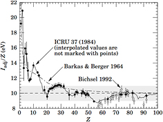
Figure 10. Dependence of the mean ionization potential I from the atomic number of the absorber. From Beringer et al, Particle Data Group (2012), copyright 2012 reproduced with permission from the American Physical Society.
Download figure:
Standard image High-resolution imageThe mean ionization potential in water is the main source of uncertainty in the stopping power and range, thus contributing to the range uncertainty. The standard value recommended by ICRU (1993) is 75 eV, but values ranging 74.6–81.8 eV are reported in the literature, with an average value I = (79.2 ± 1.6) eV (Paul 2013). The impact of changing I (from 75 to 79 eV) on the range calculation is shown in figure 11 for 200 MeV protons.
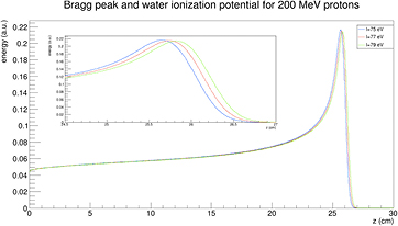
Figure 11. Impact of a ±2.5% change in the mean ionization potential I in water on the Bragg peak and range calculation. The calculation is for a 200 MeV proton beam, courtesy of Dr Andrea Fontana, INFN Pavia.
Download figure:
Standard image High-resolution imageThe mean excitation energy is a well-defined quantity in theory (Sabin et al 2013). It is indeed the first energy weighted moment of the dipole oscillator strength distribution of the target system
and using the dielectric response of the bulk system, equation (10) can be written as
Using a Drude-like dielectric function in equation (11), Emfietzoglou et al (2009) derived a theoretical value of 77.8 eV. However, in experimental dosimetry, the mean excitation energy of a bulk substance is calculated by the fit of the stopping power data from energy deposition experiments. We choose an ansatz for the stopping power or range of an ion as a function of projectile kinetic energy. The mean excitation energy is a fitting parameter determined by adjusting it to get the best fit of the ansatz function to the experimental stopping or range data. Monte Carlo programs such as FLUKA or SHIELD-HIT use this approach. But with this procedure, the mean excitation energy is not the same as the theoretical formula (10), and it depends on the ansatz and on the parameters.
The values derived in equation (3) or (4) provide an average range. The Bragg peak of a beam is of course broadened by the statistical fluctuations in energy loss, known as longitudinal straggling. The energy-loss straggling is described by the asymmetrical Vavilov distribution that, in the limit of many collisions, is approximated by a Gaussian function:

The energy-loss straggling variance σ2 in equation (12) can be used to calculate the range straggling variance as:
Equation (13) can be solved for the evolution of the range straggling variance as a function of the depth x in the material (Payne 1969):
where N is the electron density of the target and z* the effective charge of the projectile, which includes the Barkas correction (equation (2)).
The relative range straggling of a particle of energy E and mass M is nearly constant:
where ϕ is a slowly varying function, depending on the target material. For light ions stopped in water, the relative straggling is approximately 0.1%. Equation (15) provides a useful scaling law for estimating the range straggling for particles with the same range:
According to equation (16), the relative straggling for C-ions is 3.5 times smaller than for protons. For instance, the straggling at 18 cm is approximately 7 mm, which is too small to create a homogeneous target dose distribution in pencil beam scanning. To reduce treatment time, it becomes necessary to increase the straggling using a ripple filter. At the same range, the proton straggling is approximately 25 mm.
3.2. Lateral scattering
As shown in figure 4, both longitudinal and lateral beam profile spread determine the actual dose distribution in the tissues. The lateral dose distribution, which smears the initial concentrated dose in the pencil beam, is caused by the elastic Coulomb scattering with target nuclei, and by the production of secondary particles by nuclear fragmentation. Single scattering, described by the usual Rutherford formula, gives a very small deviation angle on average. Plural scattering, when the number of Coulomb scattering events increases but remains under few tens of interactions, occurs in thin targets and is the most difficult case to model. For thicker targets, lateral spread is dominated by multiple Coulomb scattering (MCS), which is well described by the Molière's theory (Bethe 1953) in term of a probability distribution function of the scattering angle θ:
where θM is the characteristic MCS angle,  is the reduced scattering angle and B is the logarithm of the effective number of collisions on the target. The functions f k of the serie expansion are related to the first-kind Bessel function of order 0, J0, by the relationship:
In the first-order approximation, k = 0, equation (17) is f 0 = 2exp(−θ'2) and therefore the Molière formula becomes a Gaussian distribution with a standard deviation given by the characteristic MCS angle (Highland 1975):
Equation (19) gives the main features of the MCS in therapy. Lateral scattering increases for thick targets (L is total mass thickness) and target materials with high atomic number Z. In fact, the radiation length is Lrad ≈ Z−2. For instance, Lrad = 36.08 g cm−2 in water, but it is only 6.37 g cm−2 in lead. For the same particle, the scattering decreases at high energy, because of the 1/(βpc) factor in equation (19). At the same range, heavier particles have smaller scattering: for instance, for 156 mm in water (150 MeV protons versus 285 MeV/n C-ions) it can be shown that (Schardt et al 2010):
According to equation (20), carbon ion beams will be three times narrower than protons in the position of deep-seated tumors (figure 7).
However, the beam profile substantially diverges from a Gaussian distribution at large angles. MCS theory can be approximated assuming that the form of the lateral beam profile comes from the combination of two processes: the electromagnetic interactions, described by Molière's theory and giving contributions to the core and to the tails of the distribution, and the nuclear interactions, contributing principally to the tails. This scheme applies both to the primary particles and to all the secondaries that are produced in the target and in the upstream beam elements. The analytic calculation of the nuclear contributions is difficult and a Monte Carlo approach is still very time consuming with the present computing technology. Therefore, many empirical parameterizations for the nuclear tails t(x) are available in literature (reviewed in Bellinzona et al 2015): single, double or triple Gaussians, Gauss–Levy, Gauss–Rutherford, Lorentz–Cauchy, and others. With this parameterization, the spread of a proton beam can be described as:
where fM(x) is the electromagnetic Molière's function (equation (17)) and Wp the fraction of events without nuclear interactions.
For protons, the dose 'halo' around the track can be divided into 4 terms: MCS, coherent (the proton interact with the whole nucleus) or incoherent (the proton interacts with single nucleons in the target) nuclear scattering, and neutral secondary radiation (neutrons and γ-rays from different nuclear reactions). Gottschalk et al (2015) have recently proposed the concise terms core for the primary beam, halo (Pedroni et al 2005) for the low dose region from charged secondaries, aura for the low dose region from neutrals, and spray for beam contamination. A set of measurements of the halo with a 177 MeV proton beam was fitted with a very accurate 25-parameter model (figure 12). Using empirical parameterization models for the proton beam at CNAO (Pavia, Italy), it was possible to get good fit of the lateral profile with the Gauss-Rutherford model (Bellinzona et al 2015), which has 4 parameters only (figure 13). This new model consists of a Gaussian core to describe the MCS and a Rutherford-like hyperbole to represent single scattering:
where the 4 parameters are the width σ of the Gaussian core, the relative weight W of the Gaussian and Rutherford contributions, the normalization factor N and the horizontal shift b of the hyperbolic function.
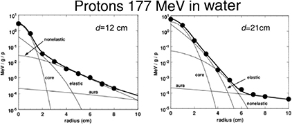
Figure 12. Lateral dose profile of 177 MeV protons at different depths d in water: 12 cm (midrange) and 21 cm (end of the range). The points are measured values at the Harvard cyclotron in Boston and the bold curve is a fit with a model-dependent function including 25 parameters. The light lines provide the contributions of the different components to the fitting function. Core, the primary beam, is a Gaussian-type function with 9 parameters. The elastic term has 4 parameters, and the nonelastic term, producing a bump in the dose at midrange at large distance from the primary beam has 9 parameters. The last 3 parameters describe the slowly varying background in the aura. Measurements and models from Gottschalk et al (2015). Reproduced with permission, Copyright 2015 IOP Publishing Ltd.
Download figure:
Standard image High-resolution image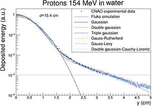
Figure 13. Lateral dose profile of 154.25 MeV protons at 15.4 cm depth in water. The points are measured values at the CNAO synchrotron in Pavia and the curves are fit with different functions or Monte Carlo simulation (FLUKA). Figure from Bellinzona et al (2015), copyright 2015 reproduced with permission from Elsevier.
Download figure:
Standard image High-resolution image3.3. Nuclear fragmentation
The nuclear fragmentation processes are essential for the calculation of the beam transport and the prediction of their effects. In proton therapy, only target fragmentation occurs resulting predominantly in secondary protons or neutrons. As shown in figure 12, inelastic scattering enhances the lateral spread of the beam. In addition, the creation of slow, densely ionizing recoil nuclei may enhance the biological effectiveness of the beam. In heavy ion therapy, fragmentation severely reduces the fluence of primary ions: in a typical C-ion therapy treatment, only 50% of the ions actually reach the Bragg peak, the others undergoing fragmentation (figure 14). In addition to the lateral spread, these secondaries contribute to the longitudinal spread of the beam (tail in figure 2). Fragmentation can be exploited as a tool for image-guided CPT (see section 5).
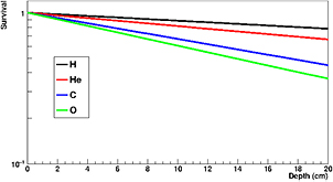
Figure 14. Survival calculated for charged particles of different mass but the same residual range of approximately 20 cm in water. To achieve the same range, the energies of the beams were: 175 MeV H, 200 MeV/u for He, 350 MeV/u for C, 400 MeV/u for O. Mean free path in water was derived from literature data as 82 cm for H, 49 cm for He, 25 cm for C, and 19.9 cm for O.
Download figure:
Standard image High-resolution imageAll nucleus–nucleus collision models used in therapy transport codes, such as the intra-nuclear cascade, molecular dynamics, etc (for a recent review see Kraan 2015) are based on the two-step picture, called cascade-evaporation, or abrasion-ablation (Hüfner et al 1975) to describe the interaction. The description of nuclear reactions through abrasion (particle removal during ion–ion interaction) and ablation (nuclear de-excitation after the abrasion step) is illustrated in figure 15, which shows the roles of projectile overlap, fireball formation in central regions, and the decay of the pre-fragment spectators. Peripheral collision leads to small mass removal, while central collisions can lead to the total destruction of the two nuclei. Ablation applies best to peripheral collisions where the remaining nuclei after the collision called the projectile or large pre-fragment are left in a state of excitation and will decay to the ground state by statistical emission of light particles and γ-rays.
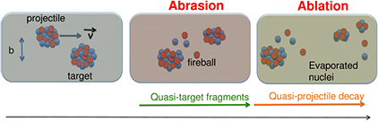
Figure 15. The abrasion-ablation model for nucleus-nucleus collisions. The relative projectile-target velocity is v, and in the laboratory frame this is very close to the beam velocity. Courtesy of Vincenzo Patera, LNF-INFN.
Download figure:
Standard image High-resolution imageThe simplest parameterization of the fragmentation process is the geometric approximation, where the nuclei are assumed to be a 'black sphere' with a radius a. The nucleus–nucleus reaction cross section, defined as the difference between total and elastic cross sections, for a projectile p on a target T is then given by:

There are several parameterizations of the nuclear radius, e.g. a = 1.2671 A1/3 − 0.152 fm for nuclei with low mass number A (Sihver et al 2014). In general, assuming that a = r0A1/3 − b, with r0 the nucleon radius and b a correction factor (overlapping factor), equation (23) can be written as the Bradt–Peters formula (Bradt and Peters 1950):
The Bradt–Peters formula is quite adequate to describe very high energy reactions (>1.5 GeV/n), but becomes less accurate at lower energies, of interest in particle therapy, where the reaction cross section shows some energy dependence. There are several corrections to equation (24) which include energy-dependent terms. In cosmic radiation transport calculations, a general expression commonly used is (Durante and Cucinotta 2011):

For instance, equation (25) is used in the NASA transport code HZETRN for cosmic radiation and the parameters have been adapted for both heavy (Tripathi et al 1997) and light (Tripathi et al 1999) ions.
A common parameterization of the Bradt–Peters formula for proton-nucleus interactions is used in the HIBRAC code (Sihver and Mancusi 2009):

where the σ0 is a Bradt–Peters geometrical factor:

and the transparency parameter b0 is a polynomial expansion of the mass target number:

For Ep > 200 MeV, equation (27) is an excellent expression for the proton-nucleus reaction cross section. It is often approximated as:

For water, equation (29) leads to NσR = 0.012 cm−1, or a mean free path λ = 82 cm. This means that protons have approximately 1% nuclear interactions per cm in water, and 20% will undergo inelastic reactions in a typical treatment plan.
At lower energies, the energy- and target- dependent function f in equation(26) becomes necessary to describe the increase of the cross section. The function has different, and quite complex shapes. For instance, for the oxygen target and 20 < Ep < 70 MeV, it can be written as:
This semi-empirical parametrization can adequately reproduce most experimental data, as shown in figure 16 for targets of interest in therapy: H2, C, O and Ca. The databases of experimental values for the proton-nucleus cross-sections for targets interesting in therapy (Carlson 1996, ICRU 2000) show many measurements in the low-energy range, but very few at Ep > 50 MeV.
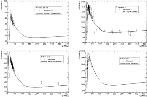
Figure 16. Fragmentation cross section of different nuclei present in human tissues by protons of different energy. The points are experimental values obtained in different tests at accelerators (Carlson 1996), the curves are the predictions based on the model in equation (26).
Download figure:
Standard image High-resolution imageMonte Carlo simulations can provide detailed information on the expected impact of target fragmentation in protontherapy. A GEANT4 simulation of a pristine 160 MeV proton beam in water is shown in figure 17 (Grassberger and Paganetti 2011). The primary protons deposit the largest part of the dose, between 90% and 99.7% of the total, depending on depth. The secondary protons account for up to 8% at a given depth and show a build-up effect due to their forward peaked emission. This effect is not visible for the heavier secondaries, since their range is much smaller. Among the other light secondaries (A < 5), only α-particles cause a significant contribution to the dose deposited, while deuterons, 3He and tritons are orders of magnitude below. Up to 0.6% is deposited by heavy secondaries (A > 4). Overall, primary and secondary protons, α-particles and heavy secondaries account for >99.9% of the absorbed dose. The same 160 MeV used in figure 17 in a phantom was simulated in a realistic prostate cancer patient to calculate the energy distributions of the recoil, shown in figure 18. Lighter fragments can have higher energy and therefore longer range in tissue. The energy distributions are highly asymmetrical, and recoils at higher energies may traverse more than one cell. The question is whether these slow recoils have high biological effectiveness, and may therefore modify the response both in the plateau and in the SOBP. In mixed radiation fields, the beam quality can be characterized by the dose-averaged LET, which is the second moment of the LET distribution or (ICRU 1970):
where Si(x) is the stopping power of the particle i at a depth x, φi its energy spectrum, and Di the dose deposited. In a GEANT4 simulation of a 62 MeV proton beam used for eye-tumor therapy, the impact of the fragments on LD was calculated (Romano et al 2014). The results show that primary protons in the entrance, plateau region have LET 1.5–2.5 keV μm−1, but the dose-averaged LET raises to 6–7 keV μm−1 according to equation (31). Along the SOBP, the primary protons LET raises from 3 to 18 keV μm−1, and the distribution is more flat when fragments are considered. In the distal part of the SOBP, the contribution of the fragments is negligible. Similar considerations apply to high-energy protons in deep tumor therapy, but the LET in the plateau will be much lower.
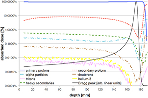
Figure 17. GEANT4 simulation of the absorbed dose as a function of depth of a 160 MeV proton beam in water. The dose is shown as percentage of the maximum absorbed dose and the individual components are shown as percentage of absorbed dose at that depth. Modified with permission from Grassberger and Paganetti (2011), copyright 2011 IOP Publishing Ltd.
Download figure:
Standard image High-resolution image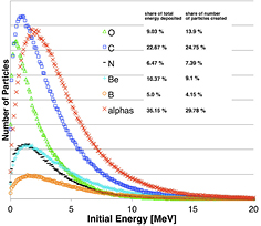
Figure 18. Energy spectra of the prevalent secondary particles (recoils and α-particles) arising from nuclear interactions in a prostate cancer patient irradiated with a 160 MeV proton beam. The inset specifies how much the specific particle contributes (in terms of energy and particle fluence) to the total energy deposited by recoils and α-particles. Modified with permission from Grassberger and Paganetti (2011), copyright 2011 IOP Publishing Ltd.
Download figure:
Standard image High-resolution imageDose-averaged LET may not represent the local effects in a very non-uniform dose deposition patterns at the μm-scale, as caused by target fragmentation. However, as shown in figure 19 (Tommasino and Durante 2015), even looking at the μm-scale, target fragmentation seems to affect more the plateau (normal tissue) than the tumor (SOBP). In figure 19, we compare the cell killing by electromagnetic interaction between target electrons and the primary proton with the cell killing due to target fragmentation, assuming that each cell where a fragmentation occurs is killed by the recoil fragments, but no neighbor cells are interested. Even if the reaction cross sections increases at low energy (figure 16), the large increase in the electromagnetic interaction in the Bragg peak covers the fragmentation effect. Target fragmentation is therefore especially a concern for normal tissue effects. Recently, a number of radiobiology experiments pointed to unexpected effects in cells or tissue exposed to protons, more similar to experiments performed with densely ionizing radiation or, especially in gene expression analysis, different from both x-rays and heavy ions (Girdhani et al 2015). It is possible that these effects are explained by the local, densely ionizing component caused by target fragmentation. The range of these particles is very small and only one or a few cells are directly hit, yet bystander effects can broaden the target and transform the local energy deposition into tissue-mediated (non-targeted) biological responses (Durante 2014).
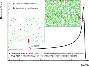
Figure 19. Cell killing caused by ionization or target fragmentation in tissue sections of 1 mm2. The LEM model was used to estimate cell survival probability assuming a fluence of 2.5 · 108 protons cm−2 for the primary beam, and a cell nucleus cross-sectional surface area of 100 μm2. This means that we can expect an average of 250 protons traversing a nucleus. In red, we show cells where target fragments are generated according to the cross section in equation (29). Under the assumption that all cells where fragmentation occurs are killed by the slow recoil fragments, red cells are killed by nuclear and green cells by electron inelastic scattering. Even though both the contributions of electromagnetic energy loss and fragmentation increase when approaching the Bragg peak, at that position the biological effect is mainly due to ionization events. On the contrary, in the entrance channel the predicted survival is high, and therefore a significant role might be played by low-energy target fragments. Figure from Tommasino and Durante (2015), reproduced with permission, CC BY 4.0.
Download figure:
Standard image High-resolution imageFor heavy ions, the projectile fragmentation becomes the main problem in the beam transport calculation, and one of the main reasons for using Monte Carlo codes. As shown in figure 14, the mean free path for C-ions is λ = 25 cm in water, and the fragments gradually build up until the Bragg peak, creating the tail beyond it (figure 20). Projectile fragments are indeed emitted especially in forward direction (very close to the primary track for Z > 2) and they have the same velocity, but lower mass, of the incident ion. In most practical cases, the tail is within the high dose region in the patient, because opposite beams are used. In single beam angles, however, their contribution to the normal tissue dose becomes non-negligible. In other words, protons stop, but heavier ions leave dust over the fence. Total charge-changing reaction cross sections of 12C-ions have been measured many times and are known with a reasonable accuracy, but double-differential cross sections are still largely missing, even if they are necessary for the benchmark of the Monte Carlo codes (Böhlen et al 2010) (figure 21). The only measurements were collected at GANIL with 95 MeV/n ions (Dudouet et al 2013) and at GSI with 400 MeV/n in a thin gold target (Pleskač et al 2012, Toppi et al 2016). Large gaps in simple reaction cross sections are found for all other ions especially at high energy in materials interesting for therapy.

Figure 20. Build-up of the C-ions fragments as a function of the depth. The yield of the heavier fragments is multiplied ×10 for comparison. Reproduced figure with permission from Schardt et al (2010), copyright 2010 by the American Physical Society.
Download figure:
Standard image High-resolution image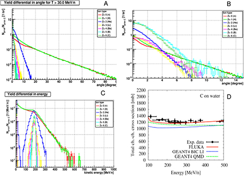
Figure 21. Simulations of the fragmentation 12C ions using the Monte Carlo code FLUKA. Fragment angular distribution dσ/dΩ at 200 MeV/n on a graphite target in the range 0–90 degrees (A) and in the restricted range 0–15 degrees (B). Fragment energy distribution dσ/dE (C). Comparison of experimental data for the total charge-changing fragmentation cross-sections of 12C in water in the energy range 100–500 MeV/n and Monte Carlo codes FLUKA and GEANT4. Images courtesy of Vincenzo Patera, LNF-INFN, modified with permission from Böhlen et al (2010), copyright 2010 IOP Publishing Ltd.
Download figure:
Standard image High-resolution imageAs noted above, equation (25) can be used for a parametrization of the projectile fragmentation cross-section. A different approach is based on the concept of factorization (Frazer et al 1972). Factorization assumes that at high enough beam energies the projectile partial charge-changing cross section, i.e. the cross section related to the probability for a projectile P to produce a given fragment F when interacting with the target nuclei T, can be written as:


In equations (32) and (33), σPF depends only on the projectile and the fragments and γ only on the target (strong factorization) or target and projectile (weak factorization). Weak factorization is one of the basic predictions in the abrasion–ablation theory, and has been experimentally verified for several measured charge-changing cross-sections for heavy ions at high energies (La Tessa et al 2007). Under the weak factorization assumption, γ can be described by a Bradt–Peters (equation (24)) term, and the cross-sections can be rescaled from a reference target Tr as:
In the HIBRAC code, hydrogen is chosen as reference target, exploiting the database on proton-nucleus cross sections discussed above (Carlson 1996, ICRU 2000) and simple interpolation formulas at high energies (e.g. equations (27) and (29)).
3.4. Other ions
As discussed in section 1.3, CPT centers are currently only using either protons or carbon ions. Several other ions have been used in the past (see paragraph 1.2), and there is a lot of discussion ongoing about the possibility of using again other ions. The idea that we still have to find the 'optimal particle' or the 'magic bullet' for curing cancer is, however, unsound. All ions share the same physics described in the previous section, and the radiobiology of several particles has been studied for decades. Therefore, no major breakthrough can be expected in using particles with 1 < Z < 6. On the other hand, very heavy ions cannot have useful applications for deep tumors. Fragmentation drastically modifies the Bragg curve, with a strong decrease of the dose in the entrance channel, more similar to photons than protons; a small Bragg peak caused by the few residual primary ions; and a long fragment tail (Durante and Cucinotta 2011). The dose reduction for very small thickness x in the entrance material can be approximated as (Durante 2014b):
In first approximation, the initial dose reduction of the Bragg curve is linear with the areal density and proportional to the fragmentation cross-section, which increases with the particle mass as A2/3 (equation (24)). The effect becomes therefore very relevant for heavy ions. Moreover, the high-LET of heavy ions in the entrance channel raises concern for normal tissue toxicity. The question is then—is it worth to look for ions different from protons and C-ions?
The rationale for using other ions is again a combination of physics and biology. From figure 7, it is clear that helium ions have much smaller lateral scattering than protons, and they are therefore expected to provide sharper dose gradients and better treatment plans, as indeed it is shown in figure 22 for a skull-base chordoma (Grün et al 2015). Helium is therefore a very attractive alternative to protons. The improved dose distributions, with limited fragmentation, would make helium elective for tumors close to OAR, where sharp gradients are needed, or for small targets in the non-cancer diseases described in section 2.4. Carbon ions had a very limited use on pediatric patients as yet, mostly because of the concern for possible second cancers caused by the high-LET exposure (Newhauser and Durante 2011). These concerns would not apply to helium, which has low-LET in the entrance channel, sharper dose gradients, and possibly an increased RBE in the SOBP that would make it more effective for radioresistant tumors. Over 2000 patients were treated with helium in Berkeley, and therefore their clinical use is already validated. Measurements of the Bragg curves in the therapeutic range (figure 23) are currently used to benchmark the beam models (Kraemer et al 2016). Fragmentation measurements would be very useful to enhance the quality of the treatment plans (figure 22).
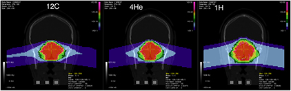
Figure 22. Treatment plan for a chordoma of the skull base for protons, helium or carbon ions. The plans are calculated with TRiP98/LEM assuming α/β = 2 Gy for both late toxicity in the brain and the tumor target. Adapted from Grün et al (2015), copyright 2015, reproduced with permission from the American Association of Physicists in Medicine.
Download figure:
Standard image High-resolution image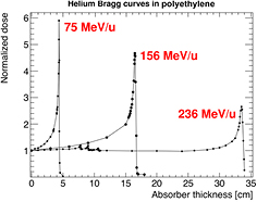
Figure 23. Measured Bragg curves for helium ions of 75, 156 and 236 MeV/n in high density (ρ = 0.97 g cm−3) polyethylene. Curves measured at the NASA Space Radiation Laboratory of the Brookhaven National Laboratory (Upton, NY, USA), courtesy of Dr Chiara La Tessa, BNL, USA.
Download figure:
Standard image High-resolution imageOxygen would be even better than carbon for the lateral scattering, but will undergo more fragmentation. At high energy, inelastic nuclear interactions will significantly reduce the entrance dose (figure 24). However, the dose-averaged LET on the SOBP will be higher for 16O than for 12C, and this causes a significant reduction of the oxygen enhancement ratio (OER; see section 1.2). The rationale for using 16O is therefore based on the reduced OER, and thus on the possibility to overcome resistance of very hypoxic tumors, or to improve effectiveness in hypofractionation, where re-oxygenation is reduced or even absent for high-dose single-fraction treatments.

Figure 24. Measured Bragg curves for oxygen ions of 284 or 600 MeV/n in high density (ρ = 0.97 g cm−3) polyethylene. Y-axis: relative dose; x-axis: depth in cm. Curves measured at the NASA Space Radiation Laboratory of the Brookhaven National Laboratory (Upton, NY, USA), courtesy of Dr Adam Rusek, BNL, USA.
Download figure:
Standard image High-resolution imageThe choice of carbon ions was mostly based on the plateau-to-peak ratio. Comparing different ions, the results will depend on the beam geometry, RBE model, and sensitivity (α/β ratio) of the tumor and the normal tissue. In figure 25, we compare two cases: uniform sensitivity −α/β(target) =  /β(normal tissue) = 2 Gy (panel B), and sensitive target −α/β(target) = 10 Gy,
  /β(normal tissue) = 2 Gy (panel C). In both cases, the tumor is irradiated with two opposite fields, as in figure 22. In figure 25(A), the physical dose released by the different charged particles is compared for the delivery of 2 Gy homogeneous dose to the target. In this case, we notice that, for the same dose to the target, a higher dose to the surrounding normal tissues is released by carbon and oxygen compared to protons and helium. Biological optimization was also performed for the two configurations of target and normal tissues described above. In figure 25(B) (same radiosensitivity for tumour and normal tissue), we observe that the optimal sparing of normal tissues is obtained with helium ions. Protons release the highest biological dose in the entrance channel, while in the region proximal to the target we observe carbon and oxygen curves crossing with the proton profile and resulting in a higher biological dose. The situation changes quite drastically when considering a radiosensitive tumour (figure 25(C)). In this case, similar results are obtained with protons and helium, showing the highest peak-plateau ratio. On the contrary, clearly higher dose is released to normal tissues by carbon and oxygen. Finally, in figure 25(D) it is shown the dose averaged LET for a single beam (solid lines), compared to those ones arising from a physical dose optimization (dotted lines). For oxygen, the LET along the SOBP is >100 keV μm−1, and at this value the OER is expected to drop down to 1 (Scifoni et al 2013, Tinganelli et al 2015).
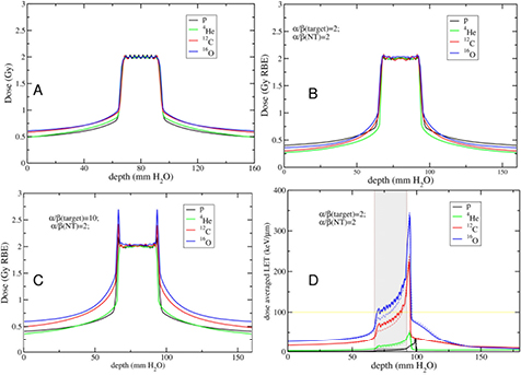
Figure 25. Double opposed field irradiation of an idealized geometry simulating a typical head and neck cancer case. The tumour (25 × 25 × 25 mm3) is centred in an irradiation volume of 16 cm length. Physical dose optimization was performed (A), as opposed to RBE-weighted dose optimization for different sensitivity scenarios (B) and (C). The dose averaged LET for a single beam is shown in panel (D) for the physical (dotted line) and biological (solid line) dose optimization. Figure adapted from Tommasino et al (2015). CC BY 4.0.
Download figure:
Standard image High-resolution imageThese results suggest that not only the physics of the different ion beams but also biological aspects strongly influence the resulting dose profiles. Therefore, the choice of the optimal ion depends on the specific tumour configuration (Remmes et al 2012, Krämer et al 2014, Grün et al 2015, Tommasino et al 2016). There is no such a thing as a 'magic bullet' but, depending on the tumour, some particles can do better than others. Multi-ion optimization in the treatment planning is feasible (Krämer et al 2014), and can lead to specific improvements. This justifies the current efforts in implementing helium and oxygen ions at HIT in Heidelberg (figure 26) and similar plans at CNAO and MedAustron.
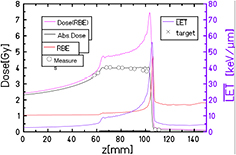
Figure 26. Depth profiles for a helium ion SOBP produced at HIT in Heidelberg. The target volume is centered at 82 mm depth, covering a depth range of 40 mm. Absorbed dose, RBE-weighted dose, RBE and dose-averaged LET depth profile were calculated with a He-beam model implemented in TRiP98. The symbols represent absorbed dose measurements. Details in Kraemer et al (2016). Reproduced with permission from Kraemer et al 2016. Copyright 2016, AIP Publishing LLC.
Download figure:
Standard image High-resolution image3.5. Summary
The physics bases of particle therapy are well understood, but the great accuracy necessary in treatment require reducing uncertainties in calculations. For the electromagnetic interaction, described by the Bethe–Bloch formula with several corrections, the main source of uncertainty remains the mean ionization potential of the target material. The lateral scattering of the beam is described by Monte Carlo or semi-empirical formulas, including both Coulomb and nuclear scattering. Nuclear fragmentation models are excellent, but they depend on reliable cross-section measurements in relevant (Ep, ZT) ranges. One of the main contributions of nuclear physics to the future of particle therapy will be the cross-section measurements, including double-differential projectile and target fragmentation cross-sections. High-precision measurements are important for protons and carbon ions, where there are already many data available, and become essential for the implementation of other ions in therapy. The two most promising species are 4He and 16O. Oxygen can play a role for very radioresistant, hypoxic tumors, while helium can find broad applications, because the lateral scattering is much smaller than protons, and the risk of normal tissue complications lower than for carbon.
4. Dosimetry
4.1. Introduction
Dosimetry is arguably the most important aspect of physics in radiation therapy. It is part of treatment planning where the goal is to administer a high dose to the tumor without compromising constraints given to critical structures. There are different constraints for different organs that are mainly based on empirical evidence. Treatment planning aims at finding the best solution for a given tumor location, geometry, and type. The main goal is always to ensure full coverage of the tumor with the prescription dose while trying to stay beyond dose constraints to OAR. For some cancers, it is not possible to achieve a tumor dose that will most likely control the tumor without exceeding dose constraints. In these cases, cure by radiation therapy is often not achievable.
The dose distribution predicted by the planning system has to reflect the dose distribution that will be delivered to the patient. Dose calculation algorithms in treatment planning systems thus have to be validated prior to their clinical use. In addition, each individual dose distribution may have to be verified prior to treatment to ensure accurate and reproducible delivery.
There are various physics processes that contribute to the absorbed dose in patients. Primary charged particles and secondary particles slowing down in the patient lose energy, leading to energy transfer to tissue and to absorbed dose. Nuclear interactions are not responsible for the Bragg peak of particle beams because the majority of dose is deposited via electromagnetic ionization and excitation. Nuclear interactions do however impact the shape of the Bragg curve because they cause a reduction in the primary particle fluence as a function of depth and dose deposited by secondary particles from nuclear interactions. As discussed in section 3.3, in proton therapy only a small contribution to dose originates from nuclear interactions. For carbon ions, the value increases to about 3% per cm range. Because of this and also because of the type of secondary particles and the much higher energy of the projectiles, the contribution of nuclear interaction products to dose is bigger in heavy ion therapy (Kempe et al 2007). Figure 27 shows a Bragg peak and the contributions of different particles for a 391 MeV/u carbon ion beam. While for a monoenergetic proton beam less than 3% of the absorbed dose is due to protons with LET > 20 keV μm−1 at the Bragg peak, ions show a considerable higher contribution which increases with the charge of the ion (Kempe et al 2007).
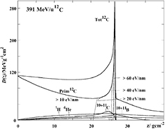
Figure 27. Depth dose distribution of a 391 MeV/u Carbon ion beam showing the primary and secondary contributions to the dose. The primary contribution is separated into different LET components. Reused with permission from Kempe et al (2007). Copyright 2007, the American Association of Physicists in Medicine.
Download figure:
Standard image High-resolution imageIn heavy ion therapy, nuclear interaction secondaries are also responsible for a tail downstream of the Bragg peak (see figure 27 and section 3.3). Nuclear interactions and the resulting secondary particles also cause a broadening of the beam, i.e. a softening of the penumbra. This has been discussed in section 3.2. For proton beams, the dose 'halo' is mainly caused by MCS, coherent scattering (the proton interact with the whole nucleus), and incoherent scattering (the proton interacts with single nucleons) (see figures 12 and 13).
The different paths of energy depositions do influence dosimetry in CPT. Dosimetry for patient treatments needs to be able to measure dose distributions as accurate as possible, at least within the desired accuracy of typically ±2.5% (ICRU 2007). The detectors being used in particle therapy are not that different from those in conventional photon therapy. Most of them rely on detecting electrons from ionization events, either created by photon or particle interactions. Nevertheless, there are some differences in particle therapy. Most importantly, the LET of particle beams is higher compared to photon beams, which can have an impact on detector response. Nuclear interactions, not present in photon beams below 10 MV photons, might have an influence on detector response as well.
Furthermore, note that the goal of dosimetry is to measure dose, a physics quantity. Not necessarily is the dose proportional to the biological effect. In particular in heavy particle CPT, one needs to consider differences in biological effect across the treatment field (as has been discussed in section 1.2), which may result in the need for delivering inhomogeneous dose distributions in order to achieve a homogeneous biological effect. This can add challenges to clinical dosimetry.
Dosimetry in radiation therapy is based on dose to water because quality assurance measurements are done in water phantoms and clinical data are based on prescription doses resembling dose to water. Furthermore, analytical dose calculation algorithms are intrinsically based on dose to water. There is a controversy whether dose to material (i.e. dose to tissue) is a more appropriate metric (Liu and Keall 2002). Dose to tissue can only be provided with Monte Carlo dose calculation, which are not yet routinely used. A conversion from dose to tissue into dose to water or vice versa is not necessarily straightforward. A conversion using the relative stopping power only deals with the electromagnetic contribution to the absorbed dose. Correction factors are required for nuclear interaction. For protons, it has been shown that an energy-independent stopping power ratio and without considering nuclear interaction events is sufficiently accurate (Paganetti 2009). For carbon ions this no longer holds. For the time being, one can expect dose to water to remain the gold standard in radiation therapy.
4.2. Absolute and reference dosimetry
Primary standards for reference dosimetry are typically set by regulatory bodies such as the National Institute of Standards and Technology (NIST) in the United States. Standard laboratories measure absorbed dose as accurately as possible under selected reference conditions. The primary standards for particle therapy are not universally agreed upon and several standard laboratories work on their own primary standard for absorbed dose measurements in CPT. There are various dosimetry protocols published by regulatory bodies, e.g. the International Commission on Radiation Units and Measurements (ICRU) (2007) or the IAEA (2000).
There is general consensus that calorimetry is the method of choice for reference dosimetry. Calorimeters measure the absorbed dose via the radiation induced temperature increase in the medium. They have been successfully applied in proton beams (Schulz et al 1992, Sassowsky and Pedroni 2005, Sarfehnia et al 2010) and carbon beams (Brede et al 2006). The main source of uncertainties are heat defects, which may depend on LET and thus effect the uncertainty in the Bragg peak region. Water calorimeters are the most popular but calorimeters based on other materials, e.g. graphite, have been built as well. They can have a higher sensitivity compared to water but the disadvantage lies in the higher thermal conductivity of graphite. Further, the dose has to be converted to dose-to-water.
For primary standard dosimetry, Faraday cups can also be utilized. Faraday Cups can measure the number of particles entering the device by collecting their charge. This includes the generated secondary particles as long as it is ensured that they cannot leave the device. Faraday Cup dosimetry has been used in proton beams (Verhey et al 1979, Cambria et al 1997, Jones et al 1999). Interestingly, Faraday cups can be more accurate in scanned beams than in scattered beams because they can cover the entire scanned field including the nuclear halo. Faraday Cup dosimetry in narrow beams have thus reached high accuracy (Grusell et al 1995, Pedroni et al 2005). Reference dosimetry using Faraday Cups has not been done for carbon ion beams though.
Ionization chambers are an alternative for reference dosimetry once calibrated against primary standards (Palmans and Vatnitsky 2015). They are not used for primary reference dosimetry because their reading depends on the energy absorbed per ion pair generated, i.e. the W value. The uncertainty in W values is on the same order as the desired accuracy of dose measurements in CPT. Furthermore, ionization chambers have a non-negligible uncertainty in chamber volume. When using ionization chambers, the dose to water is derived as the product of the charge collected in the ion chamber, factors related to the reference beam relating the ionization in the air cavity to the calibration coefficient and factors related to the ion beam relating the ionization in the air cavity to absorbed dose to water (Karger et al 2010). The latter factor consists of the product of the mean energy required to produce an ion pair, the water-to-air stopping power ratio and potentially an ion chamber perturbation correction factor (IAEA 2000).
4.3. Dose measurements in clinical practice
Dose is being measured for different purposes in radiation therapy. First, acceptance testing of a new facility is to a large extent based on dosimetry (Farr and Kruse 2015). Afterwards, the treatment delivery system and treatment planning system have to be commissioned by dosimetric measurements characterizing the radiation field for various treatment scenarios (Dong 2015). The measured commissioning data are expected to characterize the main features of the beam so that the beam penetrating the patient and its dose deposition patterns can be subsequently estimated by analytical functions in planning systems. All these tasks are done before the first patient is being treated at a new facility.
Subsequently, in clinical routine, dose measurements serve two purposes. First, they are used for quality assurance to ensure that the delivery parameters are stable (Arjomandy 2015). Second, they are performed for patient specific dosimetry measuring the dose in a thick target (typically resembled by a water phantom) relative to a delivery system setting (Arjomandy et al 2015).
Thus, the main goal of detectors in radiation therapy is to measure absolute absorbed dose. Table 3 gives an overview of detector systems in use in particle therapy. Most detector systems measure relative dose that is then related to an absolute calibration. Dosimeters are cross-calibrated against reference devices for this purpose.
Table 3. Detectors for measuring absorbed dose in CPT (from Karger et al (2010)).
| Detector | Advantage | Disadvantage | Application in ion RT |
|---|---|---|---|
| Calorimeter | Direct dose measurement | High effort, knowledge of chemical heat defect and thermal heat conduction required | Potential primary standard in the future, kQ measurements |
| Ionization chamber | High accuracy and reproducibility, small LET and energy dependence, easy to handle, many chamber types for different applications | Corrections for deviation from calibration conditions required, incomplete knowledge of corrections (chamber dependent) | Reference dosimetry, commissioning, dosimetric quality assurance, dose verification, beam monitoring |
| Films | High spatial resolution, 2D measurement | LET and energy dependence, dose cannot be obtained from optical density in mixed fields, off-line analysis required | Measurement of lateral dose profiles, beam widths, field geometry and homogeneity, documentation of beam ports |
| Radiographic films | Stability after development | Nonlinear response, daylight sensitivity, stable developing conditions required | |
| Radiochromic films | Linear response, no daylight sensitivity, self-developing, less LET- and energy dependent | Complex evaluation protocols, long term self-development, mechanical sensitivity | |
| Other detectors | Mostly experimental investigations | ||
| Silicon diode and diamond | High spatial resolution, high signal, electronic read-out | LET, dose rate and energy dependence | Lateral profile measurements |
| TLD | High spatial resolution | LET and energy dependence, off-line evaluation | Point measurements, in vivo dosimetry |
| OSL detector | High spatial resolution, linear response, repeated electronic read-out | LET and energy dependence | Point measurements, profiles |
| Alanine detector | Nearly water-equivalent, linear response | LET and energy dependence, off-line evaluation with electron spin resonance | Point measurements |
| Scintillating screen | High 2D spatial resolution, linear intensity-independent response, electronic read-out | LET and energy dependence, large device | 1D/2D distributions, field homogeneity, beam width, dose verification |
| Amorphous silicon detector | High 2D spatial resolution, linear response, electronic read-out | LET and energy dependence, potential radiation damage, expensive | 1D/2D distributions, field homogeneity, beam analysis |
| GEM-chamber | High 2D spatial resolution, linear response, electronic read-out | LET and energy dependence | 1D/2D distributions, field homogeneity, beam analysis |
| Gel | High 3D spatial resolution, nearly water-equivalent | LET and energy dependence, preparation, single use, off-line evaluation | 1D/2D/3D distributions, dose verification |
| PresageTM | High 3D spatial resolution, nearly water-equivalent, read-out by optical CT | LET and energy dependence, preparation, single use, off-line evaluation, expensive | 1D/2D/3D distributions, dose verification reference |
For dosimetry in CPT, reproducibility in beam delivery as well as dosimetry has to be high. In addition to the spatial resolution, it is also desirable to have detectors that are linear with a particle energy and independent of LET and, most importantly, linear with dose in the region of interest. Depending on the task at hand, dosimetry detector systems have different specifications. For instance, the spatial resolution required when doing quality assurance measurements can be different for beam scanning compared to passive scattering. Also, the time structure of the beam delivery and thus the local energy deposition might differ in the detector geometry potentially affecting measurement accuracy. Dose-rate linearity is an important requirement in scanned beams. Furthermore, in scanned beam delivery, depending on the scanning pattern, it may take longer to accumulate the dose over time. Some characteristics, e.g. dependencies such as on LET, may not be problematic for certain quality assurance measurements where the focus is on consistency. For a complete overview of detectors used for dosimetry in particle beams the reader is referred to (Vatnitsky and Palmans 2015). Here, we summarize some of the key aspects.
The principle on which most detectors are based on is the detection of ionizations or excitations as these are the processes that are responsible for the majority of energy loss in CPT. From the many different detector systems that can potentially be used for routine clinical dosimetry, it has been shown that ionization chambers are the most practical. They are used to measure the energy fluence in the treatment head for output factor determination (as large parallel plate ionization chambers) or as small cylindrical chambers to measure in a small region ensuring electronic equilibrium in a water tank. The field size should be larger than the chamber to ensure electronic equilibrium. For beam scanning, one often uses large area ionization chambers so that the total dose delivered by a pencil can be measured including the nuclear halo. Different size ionization chambers may be used depending on the desired resolution. Smaller chambers are often used for lateral dose profile measurements where higher resolution is desired, or in general at high dose gradients. Small fields, such as those used for SRS, often require smaller chambers. Arrays of ionization chambers have been built for higher efficiency when measuring dose distributions, e.g. in 3D (Karger et al 1999, Brusasco et al 2000, Nichiporov et al 2007, Yajima et al 2009). Segmented ionization ionization chambers are also used for beam monitoring, e.g. to monitor the shape of the spot profile in beam scanning (Cirio et al 2004, Brusasco et al 1997). Furthermore, they are installed in treatment heads to impact the steering of the beam through the beamline and treatment head via feedback loops in the treatment control software. Ionization chambers do not suffer from quenching effects due to non-linearity of detector response as a function of dose at LET. This is important because, at the end of range of particle beams, the dose is deposited by lower energy particles compared to the entrance region. As dose can basically be parameterized as fluence times LET, the same dose at larger depths in tissue is deposited by higher LET and lower fluence.
Diodes are being used as well although they do suffer from a reduced response in high LET regions and are thus not ideal for dosimetry in particle beams (Grusell and Medin 2000, Kaiser et al 2010). For instance, silicon diodes have a good spatial resolution but the quenching due to LET dependency is a problem if they are to be used for purposes other than consistency checks (Koehler 1967, Onori et al 2000). This quenching effect can be overcome by some diode types (Grusell and Medin 2000). Note that diodes may also have a non-linearity with dose and dose rate or dependency on temperature. On the other hand, the potentially small volume of diodes make them of interest for radiosurgery beams (Vatnitsky et al 1999). Radiation detectors for therapy can also been made out of diamond but they as well suffer from dose rate and LET dependencies (Onori et al 2000, Fidanzio et al 2002). However, it is advantageous that these detectors are tissue equivalent and can be small.
Ionization chambers and diodes are active dosimeters because they accumulate the dose and report it while in the radiation field. There are also passive dosimeters such as radiographic films that are mainly applied for beam profile measurements or leakage measurements. Film measurements are more common in conventional photon therapy compared to CPT because the response of films does not only depend on the energy deposited but also on the fluence, and in CPT the fluence is not directly proportional to dose. Some of these issues can be overcome by careful calibration against other dosimetry systems (Moyers 2008). Films generally need a calibration curve from optical density to absorbed dose (Daftari et al 1999, Kirby et al 2010, Zhao and Das 2010). The advantage of using radiochromic films is that they are largely tissue equivalent with a stopping power very close to the one for water, which makes correction factors obsolete. Films unfortunately also face LET dependencies. The LET dependence of GafChromic films in proton dosimetry has been extensively studied (Kirby et al 2010, Zhao and Das 2010). Figure 28 show the effect of LET dependency with Gafchromic EBT film resulting in a lower response (compared to ionization chambers) in the peak region. When measuring in an SOBP, this would cause a slope in the measured SOBP plateau. Film dosimetry has been done for carbon ion therapy but it is more challenging compared to proton therapy because of this LET dependency (Spielberger et al 2003). The radiation field consists of various secondary particles with potentially different LET-response characteristics. In ions beams, very high LET particles form nuclear interactions can even saturate the local response in the film.
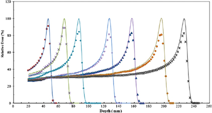
Figure 28. Depth dose distributions of pristine proton beams measured with a Gafchromic EBT film (data points) and an ionization chamber (lines). Adapted with permission from Zhao and Das (2010). Copyright 2010 IOP Publishing Ltd.
Download figure:
Standard image High-resolution imageScintillators are built of light emitting material and typically have a high spatial resolution and the advantage of instantaneous readout. Screens are frequently being designed for beam monitoring purposes in proton (Boon et al 2000) and heavy ion therapy (Furukawa et al 2008). Scintillators have been specifically suggested for small field dosimetry such as in scanned beams (Archambault et al 2008). But, as with many other detectors, significant quenching effect are difficult to correct for. As with film dosimetry, one has to rely on a constant radiation field across the position in the plane. Flat-panel imaging detectors made from amorphous silicon have been built and used to measure beam spot positions in scanned heavy ion beam delivery (Martisikova et al 2012, 2013).
Another example of passive dosimeters are thermoluminescence detectors (TLD) that accumulate dose and then can be read out afterwards as well as optically stimulated luminescence dosimeters (OSLD). Both have been suggested for CPT (Besserer et al 2001, Sawakuchi et al 2008b, Boscolo et al 2015). The latter can even monitor dose rate during irradiation because the optical readout can be very fast. There are uncertainties due to post-processing of data analysis and signal reproducibility. TLD are often used for dosimetry intercomparison between centers because they can be irradiated and then sent to standard laboratories for readout (Cho et al 2014). Also, alanine detectors have been suggested for CPT (Ableitinger et al 2013). They are linear with dose over a wide range and the material is largely tissue equivalent, both important features for clinical dosimetry. The dosimeters are made out of powder in small pellets. Ionizing radiation produces free radicals in the powder. The readout is cumbersome and so far they have been applied only for doses in excess of ~5 Gy. However, they have the advantage that they can be quite small and basically build with any geometry.
Potentially, dosimeters can also be used for in vivo dosimetry and delivery verification, which is an active research topic. Potential cavities for detector placements are the oral cavity (for head targets) or the rectum (when treating prostate) (Lu 2008a, 2008b, Lu et al 2010).
When evaluating different detector systems for dosimetry, nuclear interactions need to be considered. The importance of energy depositions originating from nuclear interactions for material conversion in proton dosimetry was outlined by Palmans and Verhaegen (Palmans and Verhaegen 2005). Inelastic nuclear interactions can cause fluence perturbations of up to 5% in the conversion of doses from the detector material to water. The dose in the Bragg peak from proton beams may only be affected by a few %, but nuclear interactions contribute considerably (up to 30%) to the dose in the entrance region of the Bragg curve (Laitano and Rosetti 2000, Paganetti 2002). This is also important when dose is measured in media other than water (e.g. in graphite calorimeters) or if dose-to-medium is desired. Laitano et al studied the influence of nuclear interactions on the proton stopping power and its effect on dosimetry (Laitano et al 1996, Laitano and Rosetti 2000). Nuclear interactions do influence experimentally determined proton stopping power ratios by up to 5% and have to be accounted for (Medin and Andreo 1997, Laitano and Rosetti 2000). The contribution of nuclear interactions is not considered when converting dose to a medium to dose to water (or vice versa) via applying simple stopping power ratios in proton beams (Paganetti 2009). A correction has to be applied for the difference in nuclear interactions that affects the particle spectrum at the point of interest. In order to correct for this, proton reaction cross sections as a function of elemental composition and atomic mass can be estimated using the parameterization by Tripathi et al (1996, 1997). The main nuclear interactions' product in a proton beam is a secondary proton, which will lose most of its energy electromagnetically. However, for heavier ions the secondary radiation field is much more complex.
Treatment planning systems that are relying on analytical (as compared to Monte Carlo based) algorithms typically utilize measured dose distributions as input kernels. Nuclear interactions contribute to the dose distributions and are thus included because they are intrinsically measured for commissioning of treatment planning systems. There is a difference though between passive scattering delivery and scanned beam delivery. The latter requires the measurement of single pencils that are then used for optimizing treatment plans in planning systems. Including nuclear interaction products in the dosimetry measurements is vital when commissioning a treatment planning system for beam scanning. Measuring the dose deposited in a single pencil may require capturing the whole pencil while, for passive scattered beam measurements, within a homogeneous dose region is preferred. The accuracy per single spot has to be much higher compared to the overall accuracy, setting higher expectations for dosimeters in scanned beam delivery. While the halo dose is low for a single pencil, it becomes significant when pencils are combined to treat a prescribed area considering that thousands of pencils may be part of a treatment field. Thus, if dose measurements are being done for treatment planning system commissioning, the halo needs to be characterized accurately. Consequently, for scanned beam commissioning, very large parallel plate ionization chambers are being used. Important are not only secondary particles generated in the phantom but also the ones generated from upstream devices in the treatment head (often called 'spray' to distinguish this contribution from the 'halo', see section 3.2). Proton beam halo measurement using ionization chambers have been reported (Sawakuchi et al 2010b, Gottschalk et al 2015). Furthermore, Monte Carlo simulations have been utilized to understand and characterize the halo for treatment planning system commissioning in proton therapy (Sawakuchi et al 2010a, Grassberger et al 2015b).
For daily treatments, the most important parameter is the dose delivered per monitor unit relating a measurement of the proton fluence as determined in a detector in the treatment head (e.g. a beam monitor consisting of a small segmented area in a parallel-plate ionization chamber) to a dose at a reference point in a water tank. In SOBP delivery, this reference point is ideally in the center of the SOBP. Monitor unit calibrations depend on the SOBPs width and range, and thus depend on the individual prescribed field so that this calibration has to be done for each treatment field. This is quite demanding in a clinical environment. Computational algorithms have therefore been developed (Kooy et al 2003, 2005, Paganetti 2006, Sahoo et al 2008). The output factor method is less robust for heavy ion treatments because the treatment fields are not homogeneous in dose (i.e. homogeneous in biological dose considering the increase in RBE as a function of depth). This is also why analytical algorithms are typically not used for heavy ion calibration, but fields are measured for each treatment. Another aspect of monitor unit calibration is that the dose in the Bragg peak decreases for small fields due to charged particle disequilibrium. This is illustrated in figure 29, which shows the effect of scattering on the central axis depth-dose curve. This effect needs to be corrected for if the output factor is not explicitly measured (Daartz et al 2009). In heavy ion therapy, one not only has to consider electronic equilibrium but also the field size dependency of the radiation quality due to secondary particles (Nose et al 2009). The above output factor considerations refer to SOBP deliveries. In beam scanning using intensity-modulation, dose distributions can be inhomogeneous. Therefore, dose is not described in cGy/MU as in passive scattering but as ions/ MU pencil by pencil. Fluence measurements are typically done indirectly via a dose measurement using an ionization chamber in the entrance region of a Bragg curve (Hartmann et al 1999).
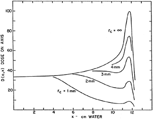
Figure 29. Depth dose distributions for a small mono-energetic proton beam assuming different dose accumulation radii on the central beam axis (unpublished graph by Koehler (1967)).
Download figure:
Standard image High-resolution image4.4. Out-of-field dose
In addition to the halo, nuclear interactions also create long-range secondary particles such as photons and neutrons, i.e. spray (see section 3.2). The neutron contribution is of particular concern because they can affect tissues far away from the target that are thus not considered in treatment planning. The dose originating from these neutrons is often referred to as 'out-of-field' dose. Neutron doses are low enough to be neglected for treatment planning, but they might still cause long-term side effects due to the elevated biological effectiveness of neutron radiation.
Cyclotrons extract a proton beam with a fixed energy causing a significant amount of secondary radiation produced in the energy selection system, which includes energy degraders of variable thickness and energy-defining slits. Degraders are built as single or multiple wedges that can move in and out of the beam. Monte Carlo beam transport through carbon and beryllium degraders has been performed with the goal of improving beam characteristics (van Goethem et al 2009). These degraders are usually outside the treatment room and do not cause secondary dose exposure of the patient. But at some facilities, fine-tuning of the beam energy (range) is done in the treatment head. Shielding calculations focus on energy fluence spectra of secondary particles (Gudowska and Sobolevsky 2005). The exact knowledge of double differential cross section for shielding material is thus very important. Shielding calculations are an important aspect when planning and designing a new facility (Ipe and Sunil 2015).
Beam scanning typically has only negligible amount of material in the beam path (unless a range shifter is used in the treatment head). This is different for passive scattering delivery. In passive scattering mode, secondary neutrons are a concern because the majority of neutrons originate in the treatment head, while the dose associated with neutrons generated in the patient is typically negligible (see e.g. Jiang et al (2005), Zacharatou Jarlskog et al (2008), Zacharatou Jarlskog and Paganetti (2008b) and Athar and Paganetti (2009))). Because of fluence loss due to nuclear interaction in the scattering system and because only a small portion of that maximum field size is used for treatment (depending on the actual size of the target to be treated), the efficiency of passive scattering treatment heads is low, typically between 3% and 30%. A high proportion of primary particles are therefore stopped in the treatment head scatterers and in particular in the patient specific aperture. Neutron production depends on the nuclear interaction cross section of the primary beam and thus on the proton beam energy and the materials in the beam path. High-Z materials are used in beam modifying devices. The complexity of field delivery in passive-scattering techniques causes considerable variations in neutron doses between facilities (Xu et al 2008). In passive scattering systems, the treatment head is variable and the settings of scatterers as well as the beam energy depends on the treatment plan, so that even for the same facility there are variations between fields. Parameters determining the neutron contamination of the beam include the characteristics of the beam entering the treatment head (energy, angular spread), the material in the double-scattering system and range modulator, and the field size upstream of the final patient-specific aperture (see e.g. Mesoloras et al (2006), Yonai et al (2008) and Zacharatou Jarlskog et al (2008). Yonai et al (2008) measured neutron doses in proton and carbon ion therapy beams.
The neutron background can be influenced by appropriately designing the treatment head, particularly for passive scattered proton beam therapy (Taddei et al 2008, Yonai et al 2008, Brenner et al 2009). In particular for small fields, the majority of neutrons reaching the patient is generated in the patient specific aperture (Jiang et al 2005, Mesoloras et al 2006, Zacharatou Jarlskog et al 2008, Hecksel et al 2010). This is because passive scattering systems can typically only deliver a fixed field size, which has to be reduced by blocking part of the beam with an aperture. Apertures are typically made out of brass, but designs can be optimized using low-Z materials and/or pre-absorbers (Brenner et al 2009).
When assessing the impact of neutron doses, not only the absorbed dose but also the neutron energy distribution is important because the biological effectiveness of neutrons depends on their energy. Neutrons with energy in excess of ~10 MeV are mainly forward-peaked. The majority of neutrons will be in the energy region below 10 MeV, produced by an evaporation process, and emitted more isotropically. Neutrons undergo very few interactions in the patient. The most likely interaction in tissue is elastic scattering. For higher energy neutrons, the energy transfer occurs mainly via secondary protons in only a few interaction events. Thus, large parts of the patient body may be exposed to a secondary radiation field. Although the neutron energy distribution peaks at low neutron energies, the majority of the neutron-generated dose is deposited by high-energy neutrons. About 2/3 of the neutron dose in a typical proton therapy scenario is deposited via neutrons with energy above 100 MeV (Zheng et al 2007b). To illustrate this, figure 30 shows the neutron energy distributions of neutrons entering a water tank downstream of a Brass block as well as neutrons causing a secondary proton in a nuclear interaction, the main mechanism of dose deposition. Fast neutron yields and fragmentation spectra have been measured in carbon beams (Gunzert-Marx et al 2004) and neutron energy distributions in patients undergoing proton therapy have been calculated using Monte Carlo simulations (Jiang et al 2005, Polf and Newhauser 2005, Zheng et al 2007a, Zheng et al 2008;).
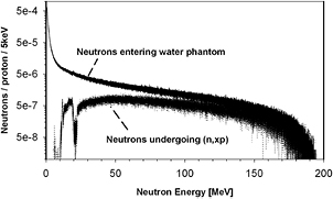
Figure 30. Energy distribution of neutrons entering a water phantom downstream of a Brass block in which all primary protons of a 200 MeV beam were stopped. Also shown is the energy distribution of those neutrons that undergo a (n,xp) reaction, i.e. those neutrons that deposit the majority of the 'neutron dose'.
Download figure:
Standard image High-resolution imageThus, Monte Carlo simulations have been applied to assess neutron dose in patients (Jiang et al 2005, Fontenot et al 2008, Zacharatou Jarlskog et al 2008, Athar and Paganetti 2009, Athar et al 2010) or studying the influence of treatment head devices and their design on neutron production (Taddei et al 2008, Brenner et al 2009). There are considerable uncertainties when it comes to simulating neutron production using Monte Carlo codes. A precise modeling of neutron yields is needed when simulating both scattered neutron doses to assess potential risks for patients (Zacharatou Jarlskog et al 2008) and neutron production for protection and shielding (Binns and Hough 1997, Fan et al 2007, Agosteo 2009).
For many neutron related studies, Monte Carlo simulations might be too time consuming because a large number histories are required to achieve a reasonable statistical accuracy. To overcome this, one might use tabulated energy dependent fluence-to-equivalent dose conversion coefficients (NCRP 1973, Boag 1975, Bozkurt et al 2000, 2001, Chao et al 2001a, 2001b, Alghamdi et al 2005, Chen 2006) in combination with calculating particle fluences at the surface of a region of interest (organ) (ICRU 1998, Polf and Newhauser 2005, Zheng et al 2007b).
4.5. Monte Carlo calculations
Monte Carlo calculations are a widely used tool in radiation therapy not only to estimate neutron background. Monte Carlo simulations are considered to be the most accurate method to compute doses or beam characteristics in radiation therapy in general. Because of the sharp dose gradients in CPT and the particles stopping in the patient leading to a finite range, the potential impact of Monte Carlo in CPT is even stronger than that in conventional photon or electron therapy. The dose depends on electromagnetic as well as nuclear interactions that are difficult to accurately describe by analytical algorithms. Particularly MCS is difficult to compute accurately and efficiently with analytical methods.
Despite its accuracy, Monte Carlo dose calculation has not found widespread use in treatment planning. There are several reasons for the limited efficiency of Monte Carlo routines. First, there is the inherent efficiency of the method itself but there is also their origin in physics laboratories where the difference in computational efficiency between hours or minutes is not as critical as in treatment planning calculations. Furthermore, Monte Carlo algorithms are not necessarily tailored to just calculating dose but are capable of studying other parameters for research purposes. Monte Carlo with high efficiency codes focusing solely on calculating dose on a patient's CT have been developed. Fast simulations are performed on graphics processing units (GPU) (Jia et al 2012, da Silva et al 2015, Giantsoudi et al 2015, Wan Chan Tseung et al 2015). It can be expected that these algorithms will be incorporated in treatment planning systems in the near future.
Thus, in the future we may see two types of Monte Carlo tools in CPT, i.e. high-efficiency Monte Carlo algorithms focusing solely on dose calculation for treatment planning and multi-purpose codes for research and development (Perl et al 2012). The latter can and will be used more and more to replace difficult or cumbersome experiments such as detector design studies for dosimetry and imaging. Simulations have been used to optimize treatment head designs in proton and carbon ion therapy and for designing experimental quality assurance procedures (Paganetti et al 2004, Parodi et al 2010, Testa et al 2013).
As mentioned earlier, Monte Carlo simulations are often used to commission treatment planning systems because they are capable of predicting beam characteristics based on the treatment head geometry (Paganetti et al 2008) and the nuclear halo for beam scanning (Grassberger et al 2015c). Pre-calculated Monte Carlo kernels can serve as input for pencil-beam algorithms and Monte Carlo predictions can influence the design of analytical algorithms, for instance to model nuclear interactions (Soukup et al 2005). Beam characterization for simulating scanned beam delivery can be done based on measured depth–dose curves in water alone, without consideration of the exact treatment head system (Kimstrand et al 2007, Grevillot et al 2011, Grassberger et al 2015b). For example, the energy spread of the beam as a function of energy can be obtained from fits of measured pristine Bragg curves. Also, for scanning, secondary particles generated in the treatment head, can typically be neglected. The application of Monte Carlo thus differs between passive scattering and scanning as well as between protons and heavy ions.
Patient specific dose simulations have to be based on CT information. Analytical dose calculation methods predict dose by modeling the physics relative to water via the relative stopping power. Monte Carlo dose calculations are based on tissue (material) compositions and mass densities and thus calculate dose to tissue. Different CT numbers can share common material properties, i.e. elemental composition and ionization potential, and may, for instance, only differ in density. Typically, each defined material (tissue) spans up to a few hundred CT numbers. The relationship between a certain CT number and a combination of materials is not unique, which leads to uncertainties (Schneider et al 2000, Espana and Paganetti 2010). Mean excitation energies for various elements (ICRU 1993) and averaged values for tissues (ICRU 1989, 1992) have been tabulated and can be interpolated based on the atomic weight of the tissue elements using Bragg's rule (see equation (9)).
Schuemann et al (2014) showed that margin reduction in proton therapy for complex patient geometries such as head, neck or lung would only be possible if treatment planning would be done with Monte Carlo. Figure 31 shows a comparison between a Monte Carlo and analytically predicted dose distribution in a proton therapy patient. Monte Carlo for treatment planning has also been suggested for carbon ion therapy (Mairani et al 2010, Parodi et al 2012). In general, one can expect the difference between analytical dose calculations and Monte Carlo to be less significant for heavier ions as far as scattering is concerned. This is simply because heavier ions scatter less compared to protons. On the other hand, differences might be bigger in areas where nuclear interactions contribute significantly such as in the fragmentation tail. However, there are potential significant uncertainties in nuclear interaction models that can affect the accuracy for heavy ion simulations (Robert et al 2013). Dose calculation in general is further more complex in heavy ion therapy because of the need to incorporate the relationship via biophysical models (Mairani et al 2010).
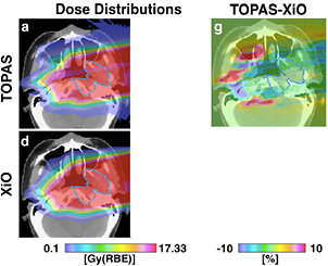
Figure 31. Dose distribution for a proton therapy patient with a tumor in the head. Upper left: Prediction by Monte Carlo (using the TOPAS code (Perl et al 2012)); Lower left: Prediction by the treatment planning system based on analytical algorithms (XiO by CMS); Upper right: Difference between the two dose distributions. Reproduced with permission from Schuemann et al (2014). Copyright 2014 IOP Publishing Ltd.
Download figure:
Standard image High-resolution imageMonte Carlo simulations need to be validated. This can be done in a clinical environment based on dosimetric measurements using, for instance, ionization chambers (Testa et al 2013). However, ideally it should not only based on therapeutic parameters such as dose but also with respect to the basic underlying physics. In radiation therapy, benchmarking of Monte Carlo simulations is typically done based on dose distributions only. In proton therapy, this might be sufficient if dose calculation is the only Monte Carlo application. For applications other than calculating the total dose, a separate benchmarking of nuclear models is necessary.
While electromagnetic interactions can typically be simulated very accurately, nuclear interaction cross sections are often associated with large uncertainties. The physics in Monte Carlo codes is mathematically defined applying models, parameterizations and/or experimental cross section data. Cross sections for nuclear interactions are typically based on look-up tables such as ENDF (Evaluated Nuclear Data File) (Chadwick et al 2011, Chadwick 2012) or EXFOR (Exchange Format) (EXFOR/CSISRS 2010) databases. Often no data exist in the energy region of interest. Furthermore, experiments were mainly done in thin targets, whereas thick targets resulting in broad energy distributions are present in CPT. Thus, often radiation therapy physics has to rely on physics settings for Monte Carlo simulations that might not be known with sufficient precision depending on the type of interaction and material (Bohlen et al 2010, Sihver et al 2012, Robert et al 2013). Radiation therapy facilities hosted in hospital environments are typically not equipped to fill the gap in cross section data. On the other hand, the underlying physics is not of particular interest anymore to today's nuclear physicists. Most data on cross section for therapeutic proton energies, for instance, are dating back to the 1960s and 1970s.
Intra-nuclear cascade models (e.g. the Bertini model) are often used for proton transport. The incident proton is assumed to undergo two-body interactions. These models are typically followed by a pre-equilibrium stage (e.g. using exciton models) to predict the emission of secondaries. Nuclear interactions by heavy ions are more complex and thus more complex to model as well. One aspect of complexity is that not only the target nucleus but also the projectile itself can break up. The abrasion-ablation approach is often used for energies of interest in therapy (see section 3.3). Despite the complexity, intra-nuclear cascade models can be used also for ions with energies in excess of 100 MeV. Models based on Quantum molecular dynamics are in use in Monte Carlo codes as well. Ablatian describes the evaporation of secondary particles typically handled by various de-excitation models. Not only secondary particle production but also their emission angle has to be described quite accurately to compute dose distributions in patients. The intra-nuclear cascade and pre-equilibrium stages can cause high-energy secondary particles that are mostly emitted in forward direction. Lower-energy secondaries are emitted more isotropically in the later stages.
Because of the difficulties to distinguish nuclear interaction models based on dose distributions, an experimental method not based on dose was suggested, i.e. the use of a multi-layer Faraday cup (MLFC) as a tool to test total inelastic nuclear interaction cross sections (Gottschalk et al 1999, Paganetti and Gottschalk 2003). It cannot be used to validate individual reaction channels but can validate the total secondary particle yield. This might be sufficient for proton therapy applications. The MLFC is sensitive to electromagnetic and nuclear inelastic reactions, and measures the longitudinal charge distribution of primary and secondary particles. Relying on charge rather than dose, it is capable of separating the nuclear interaction component (depositing charge at short ranges) from the electromagnetic component (depositing charge mainly at the end of range of the beam by particles that did not undergo a nuclear interaction). The concept of the MLC works with both, conducting (e.g. copper (Gottschalk et al 1999)) as well as insulating material (e.g. polyethylene (CH2) (Paganetti and Gottschalk 2003)). Because the experiment measures charge, not dose, it avoids issues of dosimeter linearity; its efficiency is 100%. Monte Carlo simulations can be based on the known number of particles that entered the device and do not need to be normalized. Various Monte Carlo physics models for the simulation of electromagnetic and nuclear interactions have been validated against the measured charge distribution from the MLFC, e.g. Geant4, MCNPX, SHIELD-HIT and FLUKA (Gottschalk et al 1999, Paganetti and Gottschalk, 2003, Mascia et al 2004, Zacharatou Jarlskog and Paganetti 2008a, Henkner et al 2009, Rinaldi et al 2011). As an example, figure 32 shows the comparison of measured and simulated longitudinal charge distributions in the MLFC using the TOPAS Monte Carlo code. A different Monte Carlo validation for MCS is the measurement of the nuclear halo in scanned beams as discussed in the previous section (Gottschalk et al 2015).

Figure 32. Measured (squares) and simulated (lines) longitudinal charge distributions in a MLFC for different physics settings using different nuclear interaction models in Geant4 generated with the TOPAS Monte Carlo code (Perl et al 2012). The horizontal axes show the channel in which the charge was collected. The charge is normalized to the number of protons in the beam.
Download figure:
Standard image High-resolution imageIdentifying the right nuclear models for use in Monte Carlo for carbon ion simulations is more critical because of the bigger influence of nuclear interactions on the dose distribution. Several studies for therapeutic beams have been performed (Kameoka et al 2008, Pshenichnov et al 2008) using for example the binary cascade and JQMD (Jaeri version of Quantum Molecular Dynamics) in the Monte Carlo code Geant4 and comparing the results with measurements obtained in a water phantom (Kameoka et al 2008). It was concluded that the binary cascade model was satisfactory for a 290 MeV/u beam but not for a 400 MeV/u beam (see figure 33). Furthermore, the JQMD underestimated the total dose because of a tendency to break a nucleus into lower-Z fragments compared to the binary cascade model. This shows the importance of further measurements to improve on cross section data in the energy region of interest in CPT. Fragmentation spectra in carbon ion beams were measured specifically aiming at their impact on carbon ion treatment planning because the data from the nuclear physics community are sparse (Haettner et al 2006).

Figure 33. Measured and simulated SOBPs in a 290 MeV/u (left) and 400 MeV/u (right) carbon beam. From Kameoka et al (2008), copyright 2008 reproduced with permission from Springer.
Download figure:
Standard image High-resolution imageThe requirements on validation depend on the application. For instance, fluorescent nuclear track detectors have been suggested to validate the linear energy transfer simulated by Monte Carlo for particle therapy (Sykora and Akselrod 2010, Akselrod and Sykora 2011). In those detectors, a particle track damages a polymer and an image can be extracted by chemical processing to etch the trails that can then be read out using a microscope. The dimensions of the track are proportional to LET.
Monte Carlo calculations are also being used to assess the secondary neutron background. One aspect of importance is shielding when building new facilities as discussed in section 4.4 (Ipe and Sunil 2015). Simulations have also been used to predict the neutron radiation fields in patients, which cannot be measured directly as discussed above. This application is thus very suitable for Monte Carlo simulations. Often, the dosimetry for organs outside the portion of the body that is imaged for treatment planning have to be reconstructed using whole-body computational phantoms (Xu 2014). Furthermore, dose calculation algorithms for treatment planning purposes are not commissioned for predicting low-dose radiation background. There are many Monte Carlo studies on secondary neutron radiation in particle therapy (Xu et al 2008). There are considerable uncertainties when it comes to simulating neutron production. Such simulations require double differential production cross sections for tissues, beam shaping devices and shielding materials. Because of uncertainties in cross section data for the simulations but also because of difficulties in detecting indirectly ionizing radiation, validation of neutron measurements with simulations is quite challenging (Chen and Ahmad 2009, Clasie et al 2010). Unfortunately, the experimental data on inelastic nuclear cross sections in the energy region of interest in particle therapy are scarce.
Parameterized models for Monte Carlo transport calculations based on theory in regions where experimental data are not available are often only rough estimations because of uncertainties in the physics of intra-nuclear cascade mechanisms. Consequently, agreements between Monte Carlo results and measured data have been reported to be only between 10% and 340% (Schneider et al 2002, Polf and Newhauser 2005, Moyers et al 2008, Zheng et al 2008, Clasie et al 2010). The Monte Carlo code Geant4 was applied to simulate a neutron experiment done with small ionization chambers (Clasie et al 2010). The agreement between the experiment and simulation in the out-of-field absorbed dose was within 30% at 10–20 cm from the field edge and 90% of the data agreed within 2 standard deviations. Shown in figure 34 are the simulated and experimental doses for two passively scattered proton fields. Comparisons between experiments and simulations have been done also for helium and carbon beams (Iwase et al 2007).
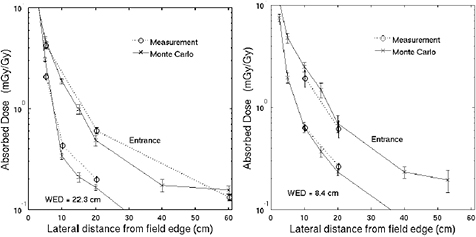
Figure 34. Simulated and experimental doses for two passively scattered proton therapy fields at different water equivalent depths. These data can be used to verify the suitability of the Monte Carlo model. Reproduced with permission from Clasie et al (2010). Copyright 2010 by the American Association of Physicists in Medicine.
Download figure:
Standard image High-resolution image4.6. Biological dose
Treatment planning is based on reaching a prescription dose to the target and meeting dose constraints for normal tissues. Thus, planning is based on the physics parameter of dose instead of on reaching certain clinical endpoints such as TCP and NTCP that are related to dose. Consequently, when treating patients with particles we need to consider the potential difference in biological effect at the same dose compared to standard photon treatments. This could be overcome by prescribing treatments for each modality independently, but would require extensive independent clinical data for each modality. As discussed in section 1.2, the RBE is defined as the ratio of photon versus proton dose to reach the same level of biological effect in a tissue assuming a homogenous dose in the region where the RBE is defined, i.e. a certain voxel in the CT. Proton therapy uses an average value of 1.1 and thus prescribed doses that are about 10% lower than the ones used in photon therapy. Variations in RBE as a function of physical as well as biological parameters are thus neglected (Paganetti et al 2002, Paganetti 2014). Variations in RBE are expected to be larger in heavy ion therapy, so that RBE values as a function of energy deposition characteristics at the region of interest as well as biological tissue parameters are being used to predict RBE values for treatment planning (Krämer and Scholz 2000, Loeffler and Durante 2013). The consequence for heavy ion therapy is that biological dose distributions rather than physical dose distributions are designed to be homogeneous in the target area.
For neutron dosimetry discussed in the previous section, one adopts conservative values for the biologically effective dose. These values are typically released by regulatory bodies. For instance, for estimating side effects from low doses in particle radiation therapy, a conservative quality factor has been defined based on the LET independent of the energy-depositing particle. Thus, it allows proper consideration of internal and external radiation. The dose equivalent is written as

The quality factor is defined as a function of the unrestricted linear energy transfer of charged particles in water (LET∞) (ICRP 2003):
For a given volume, the quality factor is obtained by integrating over the dose-weighted contributions of charged particles:
There are large uncertainties regarding the biological effectiveness of neutrons for causing long-term side effects to patients such as secondary cancers, specifically at low doses (Kocher et al 2005, Brenner and Hall 2008, Xu and Paganetti 2010, Newhauser and Durante 2011). Fortunately, the neutron background in scanned beams is typically negligible so that biological ramifications of the neutron background need to be considered mainly for passive scattering only.
4.7. Summary
Dosimetry in particle therapy is generally very similar compared to dosimetry in conventional photon or electron therapy, with its goal to ensure safe and accurate patient treatments. The same detector systems are often used. Nevertheless, caution is warranted because of the difference in the underlying physics of particle versus conventional therapy. Differences in energy deposition events, such as for example caused by particle nuclear interactions can influence detector readings. Requirements on accuracy for clinical dosimetry often exceed what is commonly achieved in nuclear physics, i.e. on the order of 1–3% in dose. Reference dosimetry to calibrate departmental detectors is thus required not only to ensure quality of treatments, but also to allow comparison of clinical outcome data. Various detectors, originally developed in physics laboratories, are being utilized depending on the desired data. For routine quality assurance, ionization chambers are the workhorse.
Because of the desired accuracy, Monte Carlo simulations have been used early on in radiation therapy for research and are now getting more and more utilized in routine clinical dosimetry and quality assurance. The accuracy of simulations is often limited by available physics data such as nuclear interaction cross sections. Data for materials relevant for cancer treatments are often sparse and obtained under thin target conditions, thus for single energies.
5. Range uncertainties
5.1. Sources
Heavy charged particles are offering an advantage in radiation therapy because of better dose conformity and reduced total energy deposited in the patient as compared to photon techniques. Both aspects are related to the finite range of a particle beam in patients. The prediction of the correct range in the patient, ideally equal to the prescribed range, is associated with considerable uncertainties due to imaging, patient setup, beam delivery and dose calculation. Table 4 summarizes some of the sources of range uncertainties and their magnitude for proton therapy. The issues are very similar for heavy ions. Uncertainties can be grouped into those that are not dose calculation related and those that are due to shortcomings in dose calculations. Clinically, a substantial range is added to the prescribed range in order to ensure tumor coverage, e.g. in proton therapy this range margin is on the order of 3.5% of the prescribed range if an SOBP is being delivered (Paganetti 2012c). For intensity-modulated therapy using beam scanning not delivering homogeneous doses per field, range uncertainties are often not explicitly considered but incorporated into robust optimization strategies designed to minimize the impact of uncertainties (Unkelbach et al 2007).
Table 4. Estimated proton range uncertainties, their sources, and the potential of Monte Carlo for reducing the uncertainty.
| Source of range uncertainty in the patient | Range uncertainty without Monte Carlo (% or mm) | Range uncertainty with Monte Carlo (% or mm) |
|---|---|---|
| Independent of dose calculation: | ||
| Measurement uncertainty in water for commissioning | ±0.3 mm | ±0.3 mm |
| Compensator design | ±0.2 mm | ±0.2 mm |
| Beam reproducibility | ±0.2 mm | ±0.2 mm |
| Patient setup | ±0.7 mm | ±0.7 mm |
| Dose calculation: | ||
| Biology (always positive)h | +~0.8% |
+~0.8% |
| CT imaging and calibration | ±0.5% | ±0.5% |
| CT conversion to tissue (excluding I-values) | ±0.5% |
±0.2% |
| CT grid size | ±0.3% | ±0.3% |
| Mean excitation energy (I-values) in tissues | ±1.5% |
±1.5% |
| Range degradation; complex inhomogeneities (negative) | −0.7% |
±0.1% |
| Range degradation; local lateral inhomogeneitiesi | ±2.5% |
±0.1% |
| Total (excluding biology and lateral inhomogeneities) | 2.7% + 1.2 mm | 2.4% + 1.2 mm |
| Total (excluding biology) | 4.6% + 1.2 mm | 2.4% + 1.2 mm |
Note: The number are estimations based on finding by aMatsufuji et al (1998) and Schaffner and Pedroni (1998). bChvetsov and Paige (2010). cBichsel and Hiraoka (1992), ICRU (1993) and Kumazaki et al (2007). dEspana and Paganetti (2010). eUrie et al (1986), Sawakuchi et al (2008a) and Bednarz et al (2010). fBednarz et al (2010). gWouters et al (1996), Robertson et al (1975) and Paganetti and Goitein (2000). The estimations are average numbers based on 1.5 standard deviations. Extreme cases, like lung, might show bigger uncertainties. Modified from Paganetti (2012).
CT scans provide a 3D image of the patient resembling the photon attenuation in the material relative to water ('Hounsfield unit') which then has to be translated into stopping power relative to water (for analytical dose calculation methods) or material compositions (for Monte Carlo based dose calculation). There are uncertainties in the conversion from Hounsfield units to tissue properties, that are reflected in uncertainties in range. First of all, the relationship is not necessarily unique. Furthermore, it may depend on the specific CT scanner and image parameters (Ainsley and Yeager 2014). Nuclear interaction contributions when determining CT calibration play a role even for protons (Palmans and Verhaegen 2005). Rietzel et al used samples of fresh animal tissues including fat, brain, kidney, liver, and several muscle tissues to study CT calibration for carbon ion treatments by measuring residual ranges behind the samples compared to ranges in water (Rietzel et al 2007).
Work has been done on dual-energy CT, i.e. utilizing CT scanners capable of scanning a patient with two different x-ray energies. Dual-energy CT does indeed improve material composition information (Bazalova et al 2008, Yang et al 2010, Hunemohr et al 2014). It has been demonstrated that Hounsfield unit conversion based on dual-energy CT reduces range uncertainties in proton and carbon ion therapy (Hunemohr et al 2014). In particular for heavy ions, the uncertainties are reduced significantly. When using dual-energy CT scanners, the electron density, and the effective atomic number are determined. The latter is the used to predict the I-value. Elemental compositions are extracted from electron density and effective charge and the mass densities are extracted from relative electron densities. This allows determining the relative stopping power.
Some of the imaging uncertainties translate directly into dose calculation. For instance, uncertainties in the tissue mean excitation energy cause errors in predicting the proton range (Andreo 2009, Yang et al 2010, Paganetti 2012b). Absolute uncertainties for human tissues mean excitation energy is large (Besemer et al 2013). However, uncertainties are typically minimized because the predicted range in water is adjusted so that it matches the measured range in water (this also takes care of uncertainties in the correct energy distribution from the accelerator). Thus, uncertainties are reduced to those relative to water.
Table 4 also distinguishes between two sources of range uncertainties from range degradation. Range degradation is caused by an increase in scatter through complex media, which is not considered in analytical dose calculation engines that are simply based on water equivalent path lengths. Complex geometries degrade the distal fall-off of Bragg peaks (Urie et al 1986). More severe are shortcomings in MCS at interfaces parallel to the beam direction ('local lateral inhomogeneities'). Thus, a clinical advantage of Monte Carlo dose calculation can be expected particularly at high-density gradients in the beam direction, such as bone/air or soft tissue/lung interfaces in a patient. The reason is that analytical algorithms typically show weaknesses in region where MCS is significant.
To correctly predict the range, accurate modeling of MCS is thus important (Schuemann et al 2014). It turns out that, in most cases, the average range across the distal fall-off in a treatment field matches very well when comparing analytical dose calculation algorithms and Monte Carlo. However, the root mean square deviation can be quite substantial. In other words, the planning system predicts a more smooth distal fall-off plane in complex geometries compared to Monte Carlo. This has implications to range margins because those margins have to be set conservatively based on the smallest range to avoid underdosing the target. Figure 35 shows an example for a proton therapy treatment plan for lung cancer. The difference in range prediction can be seen clearly due to the low lung density. Second, the absolute dose predicted might differ. The latter is typically a smaller effect, i.e. on the order of 1–5% for protons (Schuemann et al 2015).
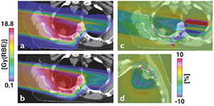
Figure 35. Monte Carlo dose calculation (a) and analytical dose calculation (b) for a lung patient treated with protons along with the difference images in axial (c) and coronal (d) view (from Paganetti et al (2015), copyright 2015 reproduced with permission).
Download figure:
Standard image High-resolution imageFattori et al investigated dose distribution variations due to setup errors and range uncertainties in carbon ion therapy of head chordoma (Fattori et al 2014). They confirmed that range uncertainties are mainly of concern for the target due to the danger of missing the tumor in situations of severe range overestimation. Schuemann et al showed that in proton therapy a reduction of current range uncertainty margins might be possible even without using Monte Carlo if site-specific instead of generic margins would be applied clinically (Schuemann et al 2014).
Note that for proton therapy, the uncertainties in nuclear interactions cross sections is not significant for clinical dose calculation because the majority of the dose is deposited electromagnetically. For heavy ions, a correct prediction of nuclear interaction channels is more significant. Furthermore, heavy ion therapy beams show a fragmentation tail that may prevent us from pointing a beam towards a critical structures, so that range uncertainties may be less consequential compared to proton therapy, where the sharp distal fall-off can be better utilized.
Another source of uncertainties in dose calculation and delivery is organ motion, for instance when treating lung cancer patients. Motion causes an overall blurring of the dose distribution and local changes in range due to high-density tumor tissue moving in and out of the field within low-density lung tissue. Thus, in contrast to photon therapy, the proton dose distribution is significantly affected by the change in patient geometry. Because of the low density of lung tissue, ranges are often reported as water equivalent path length instead of absolute distance. Water equivalent path length corresponds to substantial overshoot in the lung due to the low lung density, which is roughly a factor of 3 lower than the density of water. Thus, these fluctuations can result in an excessive dose to distal critical structures. In addition to lung tissue being replaced by higher density tumor tissue (or vice versa), rib cage motion can result in significant changes in water equivalent path lengths. Visualization of the water equivalent path length variations can be helpful during treatment planning (Mori and Chen 2008).
Another consequence of motion is an effect that is specific to scanning, the interplay effect between beam motion (within a layer or when going from one layer to the next) and organ motion (see figure 6) (Dowdell et al 2013, Grassberger et al 2013, Grassberger et al 2015a). The interplay effect does not change the mean dose to the target but will impact dose homogeneity and can thus lead to underdosage (or overdosage) of parts of the target volume, which could negatively impact tumor control (Lomax 1999, Tome and Fowler 2002).
To understand the true uncertainties and to reduce delivery errors, in vivo verification of the delivered range is desirable. To use imaging devices in order to monitor treatment is common practice in photon therapy where each beam penetrates the patient so that exit dose can be utilized. Protons or heavy ions on the other hand stop in the patient and thus imaging can only be based on secondary radiation that is being created by the primary beam. Various methods based on secondary radiation from nuclear interactions have been proposed. While standard dosimetry in particle therapy is similar to dosimetry in conventional radiation therapy, these techniques are unique to particle therapy. Some of them will be discussed in the next sections.
5.2. Positron emission tomography for range verification
Promising methods for in vivo range verification in particle therapy are based on nuclear interactions in tissue (Enghardt et al 2004, Parodi et al 2007a, 2007b, 2007c, Knopf et al 2008, Knopf and Lomax 2013). De-excitation photons or annihilation photons caused directly or indirectly by nuclear interactions are energetic enough to escape the patient and can be detected. For instance, nuclear interactions in tissue can result in positron emitting isotopes (Parodi and Enghardt 2000). Positron emitters, such as 11C (T1/2 = 20.39 min), 13N (T1/2 = 9.965 min), 15O (T1/2 = 2.037 min) and 38K (T1/2 = 7.636 min), are produced along the beam path via different channels of nuclear fragmentation reactions. These positrons annihilate with electrons after traveling a short distance (mm), thus producing two 511 keV photons. Other than in conventional PET imaging used in diagnostic radiology, the image is taken without any radiotracers, utilizing the activation of the patient by the treatment beam. Table 5 shows the nuclear interaction channels of importance for PET in vivo range verification for proton beams. Given the materials in human tissue, the positron emitters of main interest are 11C and 15O. It is important to image quickly after the patient has been irradiated because these isotopes, have half-lives of ~20 min and ~2 min, respectively. The idea to use PET for proton range verification was published already in the 1970s (Bennett et al 1975, Knopf and Lomax 2013).
Table 5. Proton-nuclear reaction channels and β+ isotopes produced in human tissues (from Espana Palomares et al (2011)).
| Target | Nuclear reaction channels | β+ isotopes | Half-life |
|---|---|---|---|
| C | 12C(p,pn)11C, 12C(p,p2n)10C | 10C, 11C | 19.29 s, 20.33 m |
| N | 14N(p,2p2n)11C, 14N(p,pn)13N, 14N(p,n)14O, | 13N | 9.96 m |
| O | 16O(p,pn)15O, 16O(p,3p3n)11C, 16O(p,2p2n)13N, 16O(p,p2n)14O, 16O(p,3p4n)10C | 14O, 15O | 70.61 s, 122.24 s |
| P | 31P(p,pn)30P | 30P | 2.50 m |
| Ca | 40Ca(p,2pn)38K | 38K | 7.64 m |
In vivo range verification in patients using ion beams has been done first at the GSI in Germany (Enghardt et al 2004) and was later introduced clinically for protons at Massachusetts General Hospital (Parodi et al 2007c). Because the dose distribution in CPT is caused by both electromagnetic as well as nuclear interactions, it is not feasible to reconstruct the entire dose distribution by detecting annihilation photons based on a subset of reaction channels. However, nuclear interaction cross sections, like the ones for interactions causing the production of positron emitting isotopes have a maximum that is typically in the energy range close to the average particle energy slightly upstream of the Bragg peak. For instance, the interaction cross section for the 12 C(p,pn)11 C reaction peaks at around 40 MeV and decreases to 0 at about 20 MeV (Espana et al 2011). As a rule of thumb, the average proton energy in the Bragg peak is roughly 10% of the initial proton beam energy entering the patient. The distal fall-off of the PET signal is thus slightly upstream of the dose fall-off at the distal edge of the Bragg peak.
Figure 36 illustrates the differences in activity profiles between different ions stopping in a plastic phantom. For protons the activity stems from isotopes generated by fragmentation of the target nuclei. For heavier ions, there is an additional contribution from beta emitting isotopes originating from the fragmentation of the primary projectile. This contribution appears near the Bragg peak, where these projectiles stop.
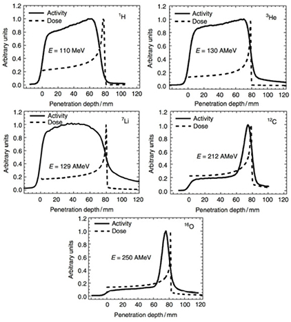
Figure 36. Measured positron emission activity together with the dose distribution for irradiation of a plastic phantom with protons, 3He, 7Li, 12C, and 16O. Reproduced from Kraan et al (2014). Copyright 2014, with permission from Elsevier.
Download figure:
Standard image High-resolution imageBecause of no direct correlation with the dose distribution, the PET image measured after the irradiation is typically compared with a Monte Carlo calculated distribution of the positron emitters. In order to increase the computational efficiency, one typically does not generate PET isotopes on a step-by-step basis in the Monte Carlo simulation but applies a conversion from proton fluence at the voxel surface to PET isotope yields by using experimental cross-sections yielding 11C, 15O, 13N, 38K and 30P. The use of Monte Carlo to predict isotope productions and thus PET images in patients has been described for protons as well as carbon ions (Pshenichnov et al 2006, Parodi et al 2007a, 2007c, Sommerer et al 2009). These simulations need to be corrected for biological washout because the activity in perfused tissues changes over time (Parodi et al 2007c, Knopf et al 2011). Furthermore, the activity is time-dependent according to the half-lives of the isotopes and the efficiency of the detector system affects the activity distribution (Parodi et al 2007a). These corrections and other uncertainties currently limit the accuracy of PET based range verification (Knopf et al 2009).
Considerable uncertainties originate from the accuracy of Monte Carlo simulation of the isotope production. The relevant cross sections are not known to sufficient accuracy because of uncertainties in converting CT Hounsfield units into material compositions in tissue (Parodi et al 2007a), but mainly because of missing nuclear physics experiments. Experiments at physics laboratories typically focus on thin targets rather than thick targets. In a patient, particle energy distributions have to be considered, while most cross section data are gathered at a few energies only (Espana et al 2011, Seravalli et al 2012, Bauer et al 2013a, Rohling et al 2013).
To validate the cross section data for nuclear interactions leading to PET isotopes and to find the cross sections data sets that better reproduce the positron emitter production with proton beams using Monte Carlo simulations, various production channels were studied independently in a heterogeneous phantom irradiated in a proton beam (Espana Palomares et al 2011). Different experimental cross sections were extracted from the EXFOR database (EXFOR/CSISRS 2010). Further, cross section recommendations were obtained from the ICRU report 63 (ICRU 2000). In addition, a combination of ICRU cross sections at low energies and one of the experimental data sets for high energies was explored. For each case, a specific channel under analysis was varied while the cross sections published by Parodi et al (2007a) were used for the remaining reaction channels (figure 37). For the 16O(p,pn)15O reaction channel, the Monte Carlo results using the ICRU cross section reproduce very accurately the fall-off region but there was a mismatch for the rest of the profile. Three different sets of cross section data were also evaluated for the 12C(p,pn)11C reaction channel. In this case, the experimental cross sections from EXFOR have about the same production energy threshold but there are differences up to 30% for higher energies. The ICRU data set results in a higher production threshold and lower absolute values. The best combination leads to a range agreement below 1 mm for in-room (immediate acquisition after treatment) measurement while close to 5 mm differences are obtained for off-line studies (long delay before acquisition). The results presented emphasize the need of more accurate measurement of the cross section values of the reaction channels contributing to the production of PET isotopes by proton beams before PET in vivo range verification method can achieve mm accuracy. Additional experimental data, in particular for the 16O(p,3p3n)11C reaction, for proton range verification are needed to reduce the uncertainties in Monte Carlo simulations (Bauer et al 2013a). The situation is similar but even more complex for carbon ions.
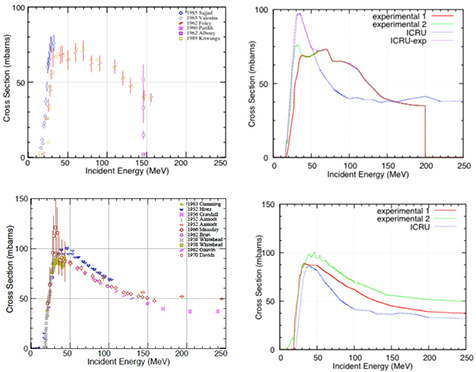
Figure 37. Cross sections for some nuclear reaction channels 16O(p,pn)15O (top) and 12C(p,pn)11C (bottom). The left column shows the experimental values (EXFOR/CSISRS 2010) while the right column shows those considered within the Monte Carlo code. Reproduced with permission from Espana Palomares et al (2011), copyright 2011 IOP Publishing Ltd.
Download figure:
Standard image High-resolution imageDespite these uncertainties, range verification using PET measurements has been done clinically in various pilot studies using proton and carbon ion beams (Kraan et al 2014). Ideally it is done during treatment (Enghardt et al 2004, Crespo et al 2006, Nishio et al 2006, 2010, Fiedler et al 2008, Shao et al 2014). Imaging in the room has the advantage of having maximum signal intensity because isotopes with short half-live are still present and due the smallest biological washout. On the other hand, scattered radiation in the room lead to background radiation particularly in passive scattering systems. Imaging during spill pauses in synchrotron systems has been done. Detectors in the treatment room are typically not available, so that most PET range verification studies are based on imaging after the treatment has been completed (Hishikawa et al 2002, Parodi et al 2007c, Hsi et al 2009, Knopf et al 2011, Bauer et al 2013b). If the imaging is done after treatment, the rapid decrease of the signal due to decay and biological washout reduces the count rate considerably (Knopf et al 2009). Images taken after treatment may only show activity from radioisotopes with a long half-life. A compromise, if there is no PET scanner installed in the treatment room, is the use of a PET scanner on wheels that can be moved into the room shortly after treatment (Zhu et al 2011, Min et al 2013). The different approaches have both pros and cons (Shakirin et al 2011). In-room scanners need specific designs to allow retrofitting of existing facilities and to not interfere with the treatment. For instance, partial ring detectors have been proposed for proton therapy (e.g. Nishio et al (2010), Surti et al (2011) and Tashima et al (2012)).
PET based range verification in proton therapy has shown accuracy of 1–2 mm in favorable locations of head-and-neck patients with tumors close to bony structures (Parodi et al 2007c). However, generally the resolution of range verification is on the order of 3–5 mm (Knopf et al 2011). In addition to improvements in cross section data mentioned above, there are various other efforts to improve the accuracy. Uncertainties also come from deducing the material compositions of tissue from CT images (Espana and Paganetti 2010). While Hounsfield unit conversion might be accurate enough for dose calculation, PET simulations are more sensitive to specific nuclear interaction channels that depend on the material composition. For example, dual-energy CT information has the potential to improve the conversion from CT numbers to material composition for PET simulations (Landry et al 2013). Furthermore, image resolution could be improved by using time-of-flight-PET detectors (Surti et al 2011). In addition, animal experiments may shed some light into uncertainties in the prediction of biological washout (Grogg et al 2015).
5.3. Prompt gamma rays and charged particle detection for range verification
A method similar in concept compared to the PET range verification idea is the use of prompt gamma radiation. This technique has been suggested for proton beams as well as Carbon beams (Polf et al 2009a, Moteabbed et al 2011a, Verburg et al 2012) and measurements as a proof of principle have been performed in proton (Min et al 2006, Polf et al 2009b, Verburg et al 2013, 2015, Testa et al 2014, Verburg and Seco 2014) and carbon beams (Testa et al 2008, 2010, Pinto et al 2015a, 2015b). After a nuclear interaction in the patient, nuclei can be left in an excited state. The resulting high-energy (~MeV) gamma radiation emitted shortly (within ~10−8 s; see Kozlovsky et al (2002)) after the excitation can be detected. Typically, the energy range between 1 and 8 MeV is targeted as it holds the main peaks for oxygen and carbon reaction channels. The energy is characteristic for the material (tissue). It has been suggested that even patient's elemental composition could be deduced using prompt gammas (Polf et al 2013).
The disadvantage compared to the PET method is the lack of a two-photon coincidence signal for 3D reconstruction. Another disadvantage, at least currently, is the lack of appropriate detector systems to detect these gammas with high efficiency and spatial resolution in a clinical setting. Thus, research on the appropriate detector design for prompt gamma range verification in CPT is ongoing (Bom et al 2012, Smeets et al 2012, Verburg et al 2013). Particularly the detector efficiency is still challenging and subject of extensive research efforts.
Different detector strategies have been applied in prompt gamma imaging for range verification, such as two-stage (Roellinghoff et al 2011) and three-stage Compton cameras (Peterson et al 2010) as well as slit-cameras (Smeets et al 2012) or time-of flight detectors (Golnik et al 2014). Recently, also spectroscopy for range verification using prompt gammas has been suggested (Verburg et al 2014).
There are several issues preventing prompt gamma to become clinical mainstream at this point. The energies of the gammas (several MeV) is quite high. Thus, photoabsorption is unlikely, leaving rather Compton scattering, pair production and single-double escape. Also, there are various gamma lines, significant background, and high flux causing issues with electronics at clinical beam currents (Perali et al 2014). Many of these problems depend on whether the method is being used in passive scattering delivery or in beam scanning.
Like PET, prompt gamma based range verification requires a comparison of the measured signal with an expected signal. The latter can only be deduced applying Monte Carlo simulations with sufficient knowledge of the underlying physics. And, like with PET, there are substantial uncertainties in cross section data for protons (Verburg et al 2012, Schumann et al 2015) and carbon beams (Dedes et al 2014).
However, the prompt gamma method also has various advantages compared to PET. For instance, prompt gammas result in a much higher count rate at production that might even allow range verification during instead of after dose delivery (Moteabbed et al 2011b) and there is no biological washout. Another advantage compared to the PET based method is that the maximum in the nuclear interaction cross sections leading to prompt gammas appear at a lower energy and thus typically closer to the Bragg peak (Moteabbed et al 2011b). Figure 38 shows a comparison between simulated dose, prompt gamma and PET signal distributions in a head-and-neck patient for proton therapy. Clearly, the prompt gamma signal resembles the dose distribution, particularly in range, more closely. The dose ranges out in soft tissue just proximal to low-density areas. Thus, one can typically expect a good correlation between prompt gamma and dose with the prompt gamma 50% falloff within 1 mm proximal to the dose falloff whereas the PET 50% falloff positions are about 5 mm proximal (Moteabbed et al 2011b).
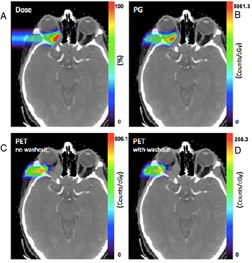
Figure 38. Dose verification using particle-induced photons on the CT image of a head and neck cancer patient. (A): dose, (B): Prompt Gamma counts, (C): PET without washout, and (D): PET with washout. Reproduced with permission from Moteabbed et al (2011), copyright 2011 IOP Publishing Ltd.
Download figure:
Standard image High-resolution imageRecently, other methods for range verification in CPT based on nuclear interactions have been proposed. The idea is that long-range secondary particles from nuclear interactions can leave the patient in heavy ion therapy (while for protons solely secondary neutrons would typically exit the patient) and could be detected (Henriquet et al 2012, Gwosch et al 2013). Feasibility studies are not conclusive.
5.4. Particle and particle CT
Range uncertainties are in part caused by translating photon attenuation imaged in CT scanners to relative stopping power for dose calculations. This uncertainty would be minimized if the relative stopping power would be measured directly using a particle beam. Proton CT is currently under development and offers a potential reduction of uncertainties in proton therapy. The idea has been along for many years but promising results have been achieved only more recently (Sadrozinski et al 2013, Plautz et al 2014). This was possible due to fast data acquisition systems and detector technologies from the high-energy physics community. The spatial resolution of proton CT is still not as good as regular CT due to MCS (Schneider and Pedroni 1994). Algorithms are being developed to improve the resolution (e.g. algorithms to predict the most likely path of a proton (Williams 2004)).
Instead of a full 3D reconstruction of the patient anatomy using proton CT, proton radiography offers an interesting solution to verify patient setup or treatment delivery (Schneider and Pedroni 1995). The idea for proton radiography is quite old and dates back to the 1960s (Koehler 1968). Proton radiography could also be used to deduce stopping power ratio (Schneider et al 2005, Doolan et al 2015). Carbon ion radiography has been done as well using an amorphous silicon flat-panel detector (Telsemeyer et al 2012). 2D distributions of water equivalent path length were measured with high accuracy.
Note that both particle CT as well as particle radiography need a higher beam energy as typically provided by today's facilities in order to penetrate the entire patient. At very high energy (0.8–2 GeV), the lateral scattering of the proton beam is largely reduced (figure 7(B)), and images can be produced using a different concept, known as high-energy proton microscopy in material research (Morris et al 2013). With a proton microscope an object is imaged using magnetic lenses: the contrast is generated by converting from MCS to transmission through the introduction of a collimator. Transmission T of the proton beam can in fact be approximated as:
where x is the target areal density, x0 the radiation length of the material, λc the nuclear collision length, and θc the angular acceptance of the microscope. Image contrast is therefore caused by a combination of MCS and nuclear interactions, and is essentially a measure of x. Because chromatic aberrations and detector blur are proportional to p−2/3 and p−1, respectively, the resolution improves by increasing the beam energy. The PRIOR project proposed at the FAIR facility in Darmstadt plans to exploit a 4.5 GeV proton beam for radiography, reaching a spatial resolution below 10 mm with a time resolution below 10 ns (Prall et al 2015b). This method can in principle be used in medicine, especially for simultaneous imaging and treatment of small lesions (Bert et al 2012). First images of biological targets have been obtained using a 800 MeV proton beam at ITEP in Moscow, Russia (Varentsov et al 2013) and at the Los Alamos National Laboratory in USA (Prall et al 2016), and this promising results suggest that very high-energy proton beams can be used for image-guided particle radiosurgery. However, beam intensities would have to be reduced significantly for these techniques, at least while imaging the patient.
5.5. Summary
Range uncertainties are a major obstacle in CPT. Considering that the finite range of particles is one of the main advantages of using heavy charged particles for therapy, accurate knowledge of the range in patients is vital to fully utilize this treatment modality. For instance, range margins currently limit the use of certain beam angles that would stop the beam right in front of a critical structure.
Methods for in vivo range verification in patients, ideally during treatment are thus desirable. This section did focus on methods based on imaging. Depending on the treatment site, detectors such as diodes could be placed in patients to detect the range based on the beam's time structure (Lu 2008a, Lu et al 2010). However, these methods are limited to small number of treatment sites.
PET and prompt gamma based range verification seem to be the most promising. The former has distinct advantages in terms of currently available technology while the latter offers the promise of more accurate range verification in the future.
6. Beam acceleration and delivery
As mentioned in section 2.5, many clinical requests go into beam acceleration and delivery. Reducing the costs call for small, compact systems. Fast and accurate beam delivery from all possible angles is another pressing request. Future facilities should be able to accelerate ions from H to Ne up to ~400 MeV/n. Pencil beam scanning is now widely adopted and will become the standard. Patient setup times are generally longer than treatment time, but with the current trend to hypofractionation, it is necessary to increase the delivery speed to reduce the treatment time. Clearly, these parameters require extensive research and development.
6.1. New accelerators
At present, the only accelerator types used for CPT are cyclotrons and slow-extracting synchrotrons (Amaldi et al 2010, Silari 2011, Amaldi and Magrin 2013, Owen et al 2014, NuPECC 2014). Research and development in the field of accelerators is often justified with the cost reduction objective. However, in reality, the beamline and gantries are more expensive than the accelerator itself. For this very reason, the dream of achieving the same cost of CPT and x-ray therapy will not be fulfilled simply by reducing the accelerator size and related costs.
Possible new accelerators for CPT include synchrocyclotrons, rapid cycling synchrotrons, fixed-field alternating gradient rings, cyclotron–linac combinations, dielectric wall accelerators, and laser-driven plasma accelerators. Table 6 shows a comparison of the main characteristics of these accelerators. These options are at very different stages of design maturity, but all offer promising design features to offset the shortcomings of current synchrotrons, including fast scanning capabilities, reduced size, complexity and power consumption, increased dose rate capability, and ultimately a lower cost and a shorter treatment time.
Table 6. A comparison of the main characteristics of the present and future accelerators for CPT.
| Accelerator | Average size (m) | Energy modulation | Repetition rate (Hz) | Energy range (MeV/n) | Ion species | In use today |
|---|---|---|---|---|---|---|
| Linacs | 50 | Modules on/off | 300 | <20 (200) | 1 (2) | Yes |
| Cyclotrons | 5 | Absorbers | CW | 70–200 | 1 | Yes |
| SC |
0.5 |
Absorbers | CW | 70–200 (400) | 1 (multiple) | Yes |
| Synchrotrons | 25 | Ramp | 0.3–0.6 | 70–430 | Multiple | Yes |
| RCMS |
20 | Ramp | 30 | 70–430 | Multiple | No |
| Cyclinacs | 30 | Modules on/off | 300 | 70 (430) | 2 | No |
| FFAG |
18 | Ramp | 1000 | (70–430) | Multiple | No |
| DWA |
2 | Modules on/off | 50 | (200) | 1 (2) | No |
| LDPA |
2–3 | Selection from full spectrum |  1 (10) 1 (10) |
58 (400) | Multiple | No |
Note: In parentheses are goals which have not been reached so far but are considered in R&D programs. aSuperconducting. bApproximately 6.3 m diameter for the C-ions prototype C400. cRapid cycling medical synchrotron. dFixed field alternating gradient. eDielectric wall accelerator. fLaser-driven particle accelerators.
Cyclotron is used in most proton therapy centres. It is popular for the simplicity of its design and its ease of use. Moreover, the availability of superconductivity technology makes it feasible with reduced size and operating costs. The cyclotrons produce continuous beams in structure and timing, and with high intensity and stability. These characteristics make cyclotrons machines designed to perform an efficient system of active scanning. Fast ignition and shutdown systems are allowed by the fast (<20 μs) acceleration process. It is possible, therefore achieving fast electronic circuits for the stabilization of intensity beam with characteristic time of 100 ms. The high stability and constancy of beam extracted from a superconducting cyclotron, allows also greater governability in terms of electronic and less technical staff employed. This finally means a significant reduction of costs design, construction and operation of the machine. Several companies in Europe, the USA and Japan are routinely delivering complete systems with cyclotrons and all other equipment. IBA (Belgium) controls the majority of the proton market with 34 cyclotrons sold worldwide. IBA (ProteusPLUS®; normal conducting; figure 39) and Varian (Probeam®; superconducting) cyclotrons operate at a field of 1.7 and 2.4 T, respectively, which is rather small in comparison with the fields up to 4–5 T of the superconducting compact isochronous cyclotrons used in several research institutes since the 1980s. This indicates that substantial room for size and cost reduction exists. Mevion Medical Systems developed a 250 MeV proton synchro-cyclotron with a field of 9 T, using novel Nb3Sn superconductor technology. This very compact cyclotron is mounted in the gantry, thus resulting in a very compact system. The first Mevion S250® is in operation in St. Louis (Mo, USA), and a half-dozen are under installation in USA. IBA has undertaken the development of a 230 MeV proton synchro-cyclotron with a field of 5.6 T. This cyclotron, called ProteusONE®, is coupled to a compact gantry with pencil beam scanning, resulting in a system with a footprint about twice as big as a treatment room for conventional radiotherapy. The pulse frequency of both machines is around 1 kHz, sufficient for the spot scanning technique. ProNova Solutions developed a superconducting isochronous cyclotron for proton therapy with a field of around 4 T, which delivers 250 MeV protons. The first ProNova SC360® has been installed in Knoxville (TN, USA). Superconducting isochronous cyclotrons are also being considered for carbon therapy and a prototype, named C400, should soon be built close to GANIL (Caen, France) by IBA and partners.
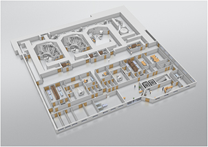
Figure 39. Drawing of the Proteus PLUS protontherapy facility commercialized by IBA. The system includes the cyclotrons, two gantries, and one fixed horizontal beamline for QA, research, or eye therapy. Courtesy of IBA, Belgium.
Download figure:
Standard image High-resolution imageThe main disadvantage of cyclotrons is represented by the inability to continuously vary the energy of the extracted beam, therefore relying on external passive absorbers for energy modulation. They are typically made of graphite and are far from the treatment room. The production of neutrons is substantial, but easy to shield and the activation is limited given the current low beam used in CPT. These modulators are sufficiently fast to allow varying the range with steps of 5 mm in 100 ms. This time is lower than that of typical of a respiratory cycle (2–4 s). It is thus always possible to implement treatment techniques controlled by the cycle of the patient's respiration (gating).
Synchrotrons are machines with a well-known technology producing pulsed beam with variable energy. Characteristics of a synchrotron used in carbon ion therapy are given in table 7, where the machine analysed is the synchrotron used in the Gunma Heavy Ion Medical Center. The machine is built and sold by Mitsubishi, which also built the heavy ion treatment centers in Hyogo and SAGA-HIMAT in Japan. By monitoring the number of cycles of acceleration it is possible to modify the energy of a few MeV. The total weight of the machine is limited, but its dimensions are always greater than 10 m and 30 m for protons and ions, respectively (figure 40). Typical repetition rate is below 1 Hz, but in the rapid cycling medical synchrotron (RCMS) prototype it should reach 30 Hz, to push the dose rate (up to 20 Gy min−1 l-1) in comparison with the current synchrotrons with acceleration period of a few seconds (Trbojevic et al 2011). The beam is then extracted pulsed temporally and its intensity is limited and not constant. Synchrotrons are more complex to use and require much attention and great experience for ensuring its efficient and reproducible operation. The possibility of changing the energy beam extraction eliminates the need of systems of external modulation. The beam produced by a synchrotron is extracted in discrete packages and typically it is present only for about half of the total time of exposure to the patient. For this reason, the scanning system must operate with double speed compared to that of a cyclotron. This implies the need to increase the power of the magnet system.
Table 7. Characteristics of the heavy ion synchrotron in operation at the Gunma Heavy Ion Medical Center for C-ion therapy in Japan.
| Ion | C6+ |
|---|---|
| Circumference | 63.3 m |
| Dipole magnets field | 0.134–1.477 T |
| Long straight section | 3.1 m |
| Injection energy | 4 MeV/n |
| Extraction energy | 140–400 MeV/n |
| Particles | 1.3 · 109 pps |
| Cycling period | 2.5–5 s |
| RF frequency | 875–6769 kHz |
| Harmonic number | 2 |
| Maximum RF voltage | 2 kV |
| Beam shut-off time | <100 μs |
| Beam extraction | Slow extraction |
Note: The machine is built and distributed by Mitsubishi.
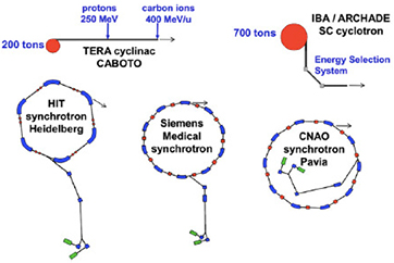
Figure 40. Comparison of the size of different heavy ion accelerators for medical applications. CABOTO is under testing by the TERA foundation. The superconducting cyclotron has been designed by IBA and a prototype is under installation within the ARCHADE project in France. HIT and CNAO synchrotrons are in operation in Heidelberg and Pavia, respectively, while SIEMENS synchrotrons are operated in Marburg (MIT) and Shanghai (SPHIC). Figure from Amaldi et al (2010), copyright 2010, reproduced with permission from Elsevier.
Download figure:
Standard image High-resolution imageHigh-frequency linacs have been proposed by Ugo Amaldi at TERA Foundation and CERN for both proton and carbon therapy (Amaldi et al 2010). In these designs, a compact isochronous cyclotron is used to deliver a proton or carbon beam that is post-accelerated to a variable energy by an independent cavity booster linac with a pulse frequency of 200 Hz. While in the initial design (CABOTO) the S-band booster linac delivered the beam to a gantry, the latest design (TULIP) proposes to integrate the linac into the gantry, requiring the use of high gradient C-band or X-band accelerating structures.
Fixed field alternating gradient (FFAG) synchrotrons are also being considered as variable energy post accelerators for particle therapy. These accelerators have a much higher repetition rate than conventional synchrotrons, while retaining the capability to change the energy at each pulse. A design study for a system with multiple independent extracted beams has been conducted in the RACCAM-project (Antoine et al 2009), while an electron model of an FFAG (EMMA) has been successfully developed at Daresbury (UK). Very significant R&D and prototype testing will still have to be done before the applicability of FFAG synchrotrons in particle therapy can be established.
Several completely new accelerator schemes are under development and may in the long run lead to still smaller sized accelerators, in particular for proton therapy. The Dielectric Wall Accelerator (Caporaso et al 2008), based on very high gradient pulses in a stack of insulating and conducting disks, would allow 200 MeV protons to be produced in a 2 m long linear accelerator rotating around the patient. The technology for this type of accelerator has been pioneered at the Lawrence Livermore National Laboratory and is now being developed further for proton therapy by the US company Compact Particle Acceleration Corporation (CPAC). The system is promising, but requires many new advances, especially the development of high gradient insulators.
Laser-driven particle accelerators (Daido et al 2012) are developing rapidly and might eventually make it possible to accelerate the particles in even smaller volumes. The laser community claims that this is the best solution for the production of benchtop accelerators for CPT (Dunne 2006). However, there are several technical problems to be solved, and in most cases they seem to be insurmountable at the least for the next decade (Linz and Alonso 2007). These problems include: verifying scaling laws for proton energy with laser power; improving proton flux by at least an order of magnitude (perhaps more than 3 for beam scanning); suitable energy distribution of the created protons; shielding for secondary radiation (especially the very abundant low-energy protons, which is likely to be bulky and expensive); target stability; improving shot-to-shot reproducibility (at least to the few % level, an objective that seems to be particularly far these days); development of suitable dose monitoring devices; development of techniques for accurate dose control and cutoff; addressing quality-assurance and patient-safety aspects. We conclude that, despite the optimistic claims, this technology will not be able to replace conventional accelerators as an effective tool in CPT anytime soon.
6.2. Beam delivery
The beam delivery system is located downstream the accelerator and is in charge of delivering the beam, preliminary to the Phantom detector (Quality Assurance), then to the patient (figure 41). It interfaces with the upstream system (ex: link with accelerator for high speed monitoring of current) and the down-stream target (ex: feedback from the motion of the organ of the patient).
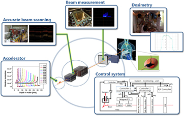
Figure 41. Position and interfaces of the beam delivery system in CPT using pencil beam scanning. The complex control system is shown in the bottom box. Image courtesy of Dr Takuji Furukawa, NIRS, Chiba, Japan.
Download figure:
Standard image High-resolution imageA substantial fraction of the cost of CPT facilities is associated with the beam delivery systems. Most of the CPT centres in operation have suboptimal beam delivery systems, that is, fixed (horizontal, vertical, and 45°) beam ports and passive beam modulation. Active scanning is preferable to passive beam modulation (figure 5), both for the improved dose distribution and for the reduction of secondary particles produced by nuclear interactions, especially neutrons, which can be responsible for adverse effects. Typical beam sizes at isocenter are 3–10 mm FWHM (depending on the beam energy), and minimum duration is 1 ms per spot. The ideal spot and grid (distance between spots) size depends on many factors including the volume treated, the protocol of delivery, and optimization of the plan (Widesott et al 2012). Spot scanning allows for intensity modulated proton therapy (IMPT), which determines individual spot intensities using an optimization algorithm that lets the user balance the competing goals of irradiating tumors while sparing normal tissue (Lomax 1999). When all spots from all fields are optimized simultaneously using an inverse optimization method, scanning allows multi-field optimization intensity modulated proton therapy (Frank et al 2014). IMPT provides the best treatment plans for protons (figure 42), and the only limits are in the proton physics, e.g. the lateral scattering.
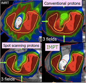
Figure 42. Treatment for a complex tumor shape using IMRT (x-rays, 9 fields), passive modulated protons (conventional protons; 3 fields), pencil beam scanning (spot scanning; 3 fields), or IMPT. Image courtesy of Tony Lomax, PSI, Switzerland.
Download figure:
Standard image High-resolution imageThe clinical implications of beam scanning were analyzed in the late 1970s and early 1980s (Grunder and Leemann 1977, Goitein and Chen 1983). Spot scanning, where the beam spots are delivered one by one with beam off time in between, covering the target volume without an aperture, was first introduced at NIRS using a 70 MeV proton beam (Tsunemoto et al 1985). Pencil beam scanning was implemented in carbon ion therapy for the first time at GSI (Haberer et al 1993) and is now also a standard in all heavy ion centers in Europe and China. NIRS in Japan has also completed the new facility with fast spot scanning (Furukawa et al 2013).
One problem in pencil beam scanning is the speed, which should be as high as possible to reduce treatment time and minimize interplay (figure 6). Increasing the beam current can reduce treatment time, and many new accelerators are designed with high intensity. However, the charge collection time of the beam monitors and the electronics dead-time limit the effective speed at high currents. Moreover, a high beam current is problematic for in vivo monitors, where the detector rate becomes too high.
Instead of increasing beam peak current, treatment time can be reduced by minimizing spill pauses or reducing the energy steps in longitudinal scanning. Larger periods and small bunch spreads are better for background reduction in prompt gamma imaging (Biegun et al 2012). The Bragg peak of protons and heavy ions is very sharp, and equation (16) shows that the straggling is too small for heavy ions, and the implementation of a ripple filter is useful to broaden the Bragg peak. This leads to fewer energy steps from the accelerator required to obtain a homogeneous dose coverage of the planned target volume (figure 43). With a synchrotron accelerator in conjunction with active scanning techniques, the use of a ripple filter is necessary to reduce the numbers of energy switches necessary to obtain a smooth SOBP, leading also to shorter overall irradiation times (Weber and Kraft 1999, Sakae et al 2000, Bourhaleb et al 2008). The dose inhomogeneity induced by the ripple filter does not seem to add uncertainties to the dose distribution and improves the lateral penumbra (Ringbæk et al 2014). Patient-specific ripple filters aiming at treatment time of 10 s l−1 are under development in research and industrial projects, and may lead to a substantial increase in scanning velocity. However, this technique requires the manufacturing of patient-specific devices, which somehow constitutes a step-back in the practice. Passive beam modulation requires patient-specific compensators (figure 5), while scanning is popular for the possibility of treating every tumor without specific components. The method would also bring additional workload, QA, and costs.
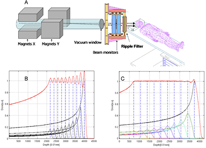
Figure 43. Ripple filters in pencil beam scanning. (A) Schematic of the beam delivery system with the position of the ripple filter. SOBP of a 70 MeV proton beam without (B) and with (C) a 3 mm ripple filter. Reproduced with permission from Bourhaleb et al (2008), copyright 2008 IOP Publishing Ltd.
Download figure:
Standard image High-resolution imageEven if less beams are used with particles than with photons, it is generally acknowledged that gantries are needed in CPT, both for improving the dose distribution and reducing the stress for the patient. Rotating gantries for proton beams are typically massive and costly (figure 39). Accommodating heavier beams, up to carbon, with similar technology requires even more massive delivery systems. Presently only one carbon ion gantry is in operation at HIT in Germany. The system is huge and very heavy (670 tons, 13 m diameter, 25 m length), and the cost at HIT eventually was similar to the cost of the accelerator and beam transport. The Danish company Danfysik designed a lighter version, still based on permanent magnets. This gantry is, however, approximately the same size as the one in HIT. Smaller gantries can only be based on superconducting magnets, and this technology is adopted by the Japanese companies. The first superconducting C-ion gantry has been installed by Toshiba at NIRS in Japan, and will be commissioned in 2016 (figure 44). This gantry is approximately half the size and weight of the HIT gantry (Iwata et al 2013), and exploits 2.0 T superconducting dipole/quadrupole magnets. Toshiba is already working on an even smaller design. However, even if reduced in size, these gantries remain expensive, need cryogenics, and have very high power consumption.
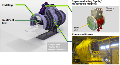
Figure 44. The 300 tons Toshiba superconducting gantry for 12C-ions. The length is 15 m and the radius 5 m. The gantry started operations in January 2016 in the new treatment facility at NIRS, in Chiba, Japan. Courtesy of Toshiba, Japan.
Download figure:
Standard image High-resolution image
6.3. Summary
The high investment and running cost of CPT is due to the large and expensive infrastructures for beam production, transport, and delivery. Cyclotrons and synchrotrons are very reliable and effective machines, and with superconducting magnets they can be made smaller and cheaper. Several novel accelerator designs are under developments, but none of them seems to be really close to entering the market. For beam delivery, pencil beam scanning is now on the market and probably future patients will be all treated with this technique, either with proton or heavy ions. Scanning, however, exacerbates the problem of moving targets, and this is a priority especially with the trend to hypofractionation. Several strategies are under study for improving the beam delivery speed, including patient-specific ripple filters. Gantries are also now generally considered indispensable for the success of clinical treatments. All proton therapy facilities have rotating gantries, and their use will be extended to heavy ions using superconducting magnets.
7. Summary and future prospects
Heavy charged particle radiation therapy has already evolved from physics research laboratories to routine clinical practice. This review summarized some of the aspects of particle therapy with special focus on the impact of nuclear interactions wherever appropriate.
While proton therapy started as a wild idea in the 1960s based on a paper from 1946 (Wilson 1946), it is no longer experimental and is here to stay. Heavy ion therapy has established itself as well, particularly in Japan. The facilities are expensive and thus a discussion on the cost-benefit ratio cannot be avoided. There is clear evidence from physics that dose distributions from particles are more favorable compared to photon or electron treatments. The total energy deposited in the patient is clearly lower when using particles. What is debatable though is whether this dosimetric advantage always matters significantly and how the dosimetric (physics) advantage translates into a clinical benefit. This question can only be answered in clinical trials analyzing patient outcome.
Some of the uncertainties in CPT are directly related to lack of knowledge in particle interactions with tissues, e.g. nuclear interaction cross sections at therapeutic energy distributions. The nuclear physics community can thus play a major role in improving CPT by providing experimental or theoretical data relevant to CPT dose calculation or detector designs. Detector systems developed in nuclear physics are increasingly utilized in CPT.
A critical aspect for future research is to gain a better understanding of radiation effects on tissues from different radiation fields because reliable biophysical models are needed in treatment planning algorithms. Another role of physics is to develop new techniques that increase the dosimetric gap between particle and conventional therapy further and to develop technology to reduce the cost of facilities.
Acknowledgments
We thank Dr Gerhard Kraft for useful discussions and Dr Francesco Tommasino for his contribution to several figures in this paper. Work in nuclear physics applications in MD lab is partly supported by the Helmholtz Association Portfolio 'Technologie und Medizin'.
Footnotes
- 5
IMRT is an advanced form of 3D conformal x-ray therapy, where the intensity of the beams is modulated to achieve a higher degree of conformality of the resulting dose distribution with the tumor target volume. The intensity of the beams that cross sensitive organs is reduced, while is increased the intensity of those beams that see primarily the target. The resulting inhomogeneities (hot/cold spots) are compensated by the beams coming from different directions.
- 6
In particle radiobiology, the stopping power (see section 3.1) is indicated as linear energy transfer (LET) and given in units of keV per μm of water.
- 7
Radiation dose is measured in J kg−1, a unit called gray (Gy). To account for the different biological effects of the same dose in Gy when delivered by photons or charged particles, the dose is multiplied by the RBE and the recommended unit is Gy(RBE). The RBE-weighted dose replaces the old units such as gray-equivalent (GyE) or cobalt-gray-equivalent (CGE). A similar approach is used in radiation protection at low doses, where radiation weighting factors are used and the equivalent dose is expressed in sievert (Sv). Because the RBE is dose-dependent, quality factors in radiation protection are generally much larger than RBE in radiotherapy.
- 8
Clinical studies are divided into phases: 0 (pre-clinical), I (safety), II (efficacy), III (randomized controlled studies to compare different modalities), and IV (safety surveillance). Only phase III trials lead to level I evidence according to the Center for Evidence-based Medicine in Oxford.