
Abstract
Cone-beam consistency conditions (also known as range conditions) are mathematical relationships between different cone-beam projections, and they therefore describe the redundancy or overlap of information between projections. These redundancies have often been exploited for applications in image reconstruction. In this work we describe new consistency conditions for cone-beam projections whose source positions lie on a plane. A further restriction is that the target object must not intersect this plane. The conditions require that moments of the cone-beam projections be polynomial functions of the source positions, with some additional constraints on the coefficients of the polynomials. A precise description of the consistency conditions is that the four parameters of the cone-beam projections (two for the detector, two for the source position) can be expressed with just three variables, using a certain formulation involving homogeneous polynomials. The main contribution of this work is our demonstration that these conditions are not only necessary, but also sufficient. Thus the consistency conditions completely characterize all redundancies, so no other independent conditions are possible and in this sense the conditions are full. The idea of the proof is to use the known consistency conditions for 3D parallel projections, and to then apply a 1996 theorem of Edholm and Danielsson that links parallel to cone-beam projections. The consistency conditions are illustrated with a simulation example.
Export citation and abstract BibTeX RIS
1. Introduction
In medical imaging, there are numerous examples of applications where data consistency conditions (also known as range conditions) play a central role in the image reconstruction step. The idea is that certain mathematical redundancies in the projection measurements can be exploited to identify the parameters of some systematic effect, such as abrupt patient movement (Welch et al 1998, Yu and Wang 2007, Leng et al 2007), beam-hardening scaling factors (Tang et al 2011), attenuation factors in emission tomography (Natterer 1983, Hertle 1988, Welch et al 2003, Defrise et al 2012), unknown patient outline (Natterer 1993, Laurette et al 1999, Mennessier et al 1999), or to synthesize missing projections (Defrise 1995, Patch 2002b) or missing rays of truncated projections (Erlandsson et al 2000).
The data consistency conditions themselves are mathematical relationships that precisely describe the redundancies in the projection data. The Helgason–Ludwig (HL) conditions (Helgason 1980, Ludwig 1966) for parallel projections in classical two-dimensional (2D) tomography are well known. Consistency conditions are also known for exponential projections (Aguilar and Kuchment 1995) and for attenuated projections (Natterer 1983) with applications in single photon emission computed tomography (SPECT) imaging. For fanbeam rather than parallel projections, various descriptions of consistency conditions have been published (Finch and Solmon 1983a, Louis and Rieder 1989, Patch 2001, Chen and Leng 2005, Yu et al 2006, Mazin and Pelc 2010, Clackdoyle 2013).
Necessary consistency conditions are any description of the redundancy in ideal projection data; they are consequences of the mathematical relationship between the unknown object and its projections. Sufficient consistency conditions are enough conditions on the projections to ensure that they are compatible with some object function. We say that a set of conditions is full if the conditions are both necessary and sufficient. The significance of full consistency conditions is that no more independent conditions are possible; in this sense, full conditions are complete. However, there can be different descriptions of consistency conditions. The HL conditions are full, but there are other conditions such as those given by the frequency-distance principle (Edholm et al 1986). All such other conditions for 2D parallel projections can in principle be expressed in terms of the HL conditions. For image reconstruction applications, usually a relatively small set of necessary conditions are applied.
In this work, we are concerned with cone-beam consistency conditions. Cone-beam projections arise in x-ray systems and in SPECT imaging with pinhole collimators. Our aim is to demonstrate new cone-beam consistency conditions, but we do not develop specific applications for them here. Similar to the HL conditions for parallel projections, we will show how moments of the cone-beam projections are related to each other. The cone-beam moments however, do not present a simple relationship to the moments of the object function, such as occurs in the case of parallel projections. Our derivations are only applicable for cone-beam sources on a plane, with the added restriction that the object must not intersect the source plane. However, we are able to provide full (necessary and sufficient) consistency conditions, and the main contribution of this work is the mathematical demonstration that the conditions are sufficient. The conditions described here have been announced at the 12th International Meeting on Fully 3D Reconstruction in Lake Tahoe (Clackdoyle and Desbat 2013), but no formal proof of these conditions was given.
Cone-beam consistency conditions have been studied intermittently for some time. In 1938, John published full consistency conditions in terms of a system of second-order partial differential equations (John 1938). The local nature of the differential equations makes them awkward for applications, although Patch has succeeded, using numerical techniques, in applying these conditions for synthesizing unmeasured projections from the available measured data (Patch 2002b). In 1985, Finch was the first to express John's equations in the Fourier domain to obtain a cone-beam reconstruction procedure based on synthesizing projections (Finch 1985). An implementation of this method was described in (Chen 1992), with extensions to regional tomography. Patch started with John's equations and followed Finch's approach, but applied the consistency conditions to an 'open-gantry' cone-beam reconstruction problem, and emphasized the mathematical property that the cone-beam projections must be constant along certain lines in the Fourier domain (Patch 2002a). Levine et al followed (Patch 2002a) and went further by pointing out a beautifully simple cone-beam consistency condition for a source moving along a line parallel to the detector (Levine et al 2010). The condition can be interpreted as a fanbeam result for multiple lines on the detector parallel to the source line, and can be seen as a zero-order condition (Clackdoyle 2013).
Approaches that are not directly related to John's equation include that of Finch and Solmon (Finch and Solmon 1983a) who gave full consistency conditions for sources on a sphere, essentially by re-expressing the conditions for 3D parallel projections into cone-beam variables. In a different work, Finch and Solmon (Finch and Solmon 1983b) considered finite collections of cone-beam projections and gave full consistency conditions under the restriction that no three sources were collinear, which is more restrictive than the situation we consider here. The fundamental cone-beam formulas of Grangeat and Smith (Grangeat 1987, 1991, Smith 1985, 1990) can be interpreted as consistency conditions. In both cases a transformed cone-beam projection can be related to a filtered form of the three-dimensional (3D) Radon transform of the unknown object function, thereby providing a redundancy link between different projections. However, the Grangeat formula gives no information about sources on a common plane unless this plane intersects the object, which is not the case under consideration here.
A common feature of many of the cone-beam consistency conditions in the literature is that they provide a method of synthesizing cone-beam projections for virtual sources located inside a circle of measured sources. Carlsson et al also demonstrated how to synthesize cone-beam projections from sources inside a circle (Carlsson et al 1994) but their method was based on the Fourier slice theorem for 3D parallel projections and a theorem published by Edholm and Danielsson (Edholm and Danielsson 1996) that links cone-beam and parallel projections. This theorem plays a central role in our proof of sufficient consistency conditions. The theorem concerns cone-beam projections on a flat detector from source positions located on a plane parallel to the detector. Edholm and Danielsson proved that these cone-beam projections are identical to the parallel projections of a different object.
Our main result is based on the observation that the Edholm–Danielsson theorem implies that consistency conditions for parallel projections on a flat detector must be the same as the consistency conditions for cone-beam projections. In the next section, we provide a formal mathematical proof of this result. We begin by recalling the known consistency conditions for 3D parallel projections, and we convert these conditions to the equivalent version for parallel projections striking an immobile flat detector. We use the Edholm–Danielsson theorem to convert these conditions to cone-beam conditions on the flat detector, and we then adjust these conditions to a more convenient description of cone-beam projections. In the following section we develop the consistency conditions further, and show how moment conditions can be obtained. We then provide simulation examples to illustrate the behavior of these conditions. In the final section we provide a brief discussion and conclusion.
2. Derivation of cone-beam consistency conditions
In this section we state cone-beam consistency conditions for sources on a plane, and we provide formal derivations that these conditions are full (necessary and sufficient).
In the five theorems stated below, the first two concern 3D parallel projections, the third is a slightly adapted version of the Edholm–Danielsson theorem, and the last two theorems concern cone-beam consistency conditions. Theorem 1 is a standard theorem for 3D parallel range conditions, and theorem 5 is the objective of this section, the new theorem for cone-beam range conditions. The work pivots on theorem 3 which shows how the parallel-beam projections of one object can match the cone-beam projections of a second object if it is defined in a special way. Theorems 2 and 4 are intermediate formulations, expressed in the geometry required for theorem 3.
We begin with consistency for 3D parallel projections. For an unknown density function f(x, y, z), the parallel projection  is defined by

where the angular variables θ ∈ [0, π/2], ϕ ∈ [0, 2π) specify the integration direction of the projection by γ = γθ, ϕ = (cos ϕsin θ, sin ϕsin θ, cos θ). The triple γ, α, β are three mutually orthogonal unit vectors, with α, β indicating the (s, t) directions on a conceptual detector passing through the origin and oriented perpendicularly to γ. We explicitly define α = αθ, ϕ = ( − sin ϕ, cos ϕ, 0) and β = βθ, ϕ = ( − cos ϕcos θ, −sin ϕcos θ, sin θ).
Full consistency conditions for 3D parallel projections have been known for some time (Solmon 1976, Helgason 1980, Finch and Solmon 1983a, Natterer 1986). Ignoring details concerning the precise function spaces concerned, and expressing the theorem in our notation, we obtain
Theorem 1. For each n = 0, 1, 2..., we define Qn in terms of p by

Then  for some compactly supported f if and only if p(θ, ϕ, ·, ·) has compact support for all θ, ϕ, and for each non-negative integer n,

for some homogeneous polynomial Rn(X, Y, Z) of degree n.
We remind the reader that for a homogeneous polynomial of degree n in three variables X, Y, Z, each term is of the form ci, j, k XiYjZk with i + j + k = n. Throughout this work, the coefficients ci, j, k of the polynomials will be real numbers (not complex).
Although these facts are not used in the following, we make the following comments. From the definition, Qn(θ, ϕ, ·, ·) is already a homogenous polynomial of degree n in two variables. Equation (3) is reminiscent of the Fourier slice theorem, and a geometric interpretation is that Qn(θ, ϕ, ·, ·) is a 2D central section (perpendicular to γθ, ϕ) of some 3D function Rn. Theorem 1 further requires that this 3D function also be a homogeneous polynomial of degree n.
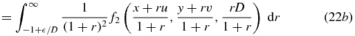
The first step is to convert this theorem to the case of a flat virtual detector whose orientation does not change with θ, ϕ. We let our detector lie in the x–y plane, so the projection variables (s, t) will be converted to (x, y), while taking into account the obliqueness of the projection direction. Also, a weight will be applied to each projection, to anticipate the hypotheses of the Edholm–Danielsson theorem. Thirdly the direction of each projection will no longer be expressed using the angular variables (θ, ϕ), but using linear variables (u, v) whose definition will depend on a positive scalar D. When these substitutions have been made we will have defined 3D parallel projection data  onto a flat detector by

where the projection weight is (cos θ)/D. Figure 1 illustrates the change of geometry, and the details of the variable changes are as follows.

Figure 1. (a) Changing from (s, t) to (x, y). The s–t detector is perpendicular to the integration line, which is parallel to γ. The (x, y) detector coordinates are found by projecting the point (s, t) along the integration line onto the x–y plane. (b) Changing from to (θ, ϕ) to (u, v). The integration direction γ is initially specified using (θ, ϕ). The vector (u, v, D) is proportional to the unit vector γ.
Download figure:
Standard image High-resolution imageThe fixed detector variables (x, y) are given in terms of standard projection variables (s, t) by


and, for any choice of fixed D > 0, the new linear variables (u, v) are defined in terms of the angular variables (θ, ϕ) by


as illustrated in figure 1.
Now beginning with equation (4), and using equation (1) with equations (5) and (6) we find that

and we write equation (7) as  for short.
One path to equation (7) is to begin with the integral of equation (1) and change integration variables using r' = r + ttan θ so r' = 0 corresponds to where the integration line intersects the x–y plane. Then the variables can be changed according to equations (5) and (6). One further change of integration variables is required, such as r'' = r'(cos θ)/D (or equivalently,  ) which indicates how the projection weight (cos θ)/D appears. Equation (7) then follows from the definition of
  , equation (4). Thus we have proved, for any D > 0, that
  if and only if
  .
.
Theorem 1 can now be converted to the form we need.
Theorem 2. For each n = 0, 1, 2..., we define  in terms of
  by
by

Then for every D > 0, we have  for some compactly-supported f if and only if
  has compact support for each
  , and for each non-negative integer n,

for some homogeneous polynomial  of degree n.
Theorem 2 is essentially a rewriting of theorem 1. Recalling that


(where Rn is some homogeneous polynomial of degree n), we see that theorem 2 is proved if we complete the chain of equivalences by demonstrating that, for all n = 0, 1, 2...,


for some homogeneous polynomial  of degree n.
We first relate Qn to  as follows. Starting with equation (8) we change (u, v) to (θ, ϕ) using equation (6), and then apply equation (4) while changing the integration variables from (x, y) to (s, t) using equations (5). We thus obtain


so we have shown that


From equations (11a) and (13a), we have that


where S and T are the expressions given in equations (13b) and (13c). Evaluating Sα + Tβ and simplifying yields


Using equation (6) in equations (14b) and (15b) gives us that


so let  and the proof is complete.
To provide some geometric interpretation to equation (9), we note that the use of linear variables (u, v) to indicate the projection direction is very similar to the planogram format (Brasse et al 2004), and that the planogram version of the Fourier slice theorem is described very similarly to equation (9). See equation (23) in (Brasse et al 2004).
We now turn to the Edholm–Danielsson theorem on divergent projections (Edholm and Danielsson 1996). The statement and proof of this theorem have been slightly adapted for our needs.
Theorem 3. Let f1 be a density function with compact support lying in the half-space z > −D (therefore f1(x, y, z) = 0 for z ⩽ −D +  for some small positive ). Suppose that

(i.e. suppose that  ) then there exists a function f2 with compact support in the half-space z < D such that for all real values of u, v, x, y,

Figure 2 illustrates the geometry. Conceptually, the x–y plane is the detector, and parallel x-ray projections are taken of f1 at the angle defined by (u, v) as shown in the diagram. These same detector measurements also correspond to the cone-beam projections with source point located at (u, v, D) on the plane z = D of some different density function f2. Only one pair of density functions is needed, and the equality holds for all projections (for all (u, v)).
To prove theorem 3 we immediately define f2 in terms of the given function f1 by


(Remark: M is the magnification factor at a point z for a source on the z = D plane with a detector plane z = 0.) From the support condition for f1, we have f1(Mx, My, Mz) = 0 for Mz ⩽ −D + so we obtain f2(x, y, z) = 0 for z ⩽ D( − D)/. The support of f2 is therefore contained in the region D − D2/ < z < D. This support range for f2 will be needed below, as well as the inverse relationship between f1 and f2, which is


The integrand of equation (17) is

as seen by setting x' = x + ru, y' = r + rv, z' = rD and applying equations (20). Also, the lower integration limit of equation (17) can be changed from −∞ to −1 + /D since f1(x + ru, y + rv, rD) vanishes for rD ⩽ −D + . Therefore,


where we have performed the substitution r' = 1/(1 + r) and therefore 1 − r' = r/(1 + r). In equation (22d), the upper integration limit has been extended from D/ to ∞ because, recalling the support of f2, the integrand vanishes for r > D/. The theorem is thus established.
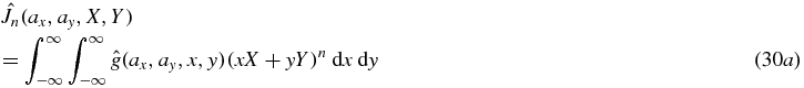
The next two theorems provide consistency conditions for two different definitions of cone-beam projections. For a function f whose compact support lies in the upper half space z > 0 we define


In equation (24), which is the conventional form of the divergent beam transform, we will only be concerned with source points a that lie on the z = 0 plane, so a = (ax, ay, 0). These two definitions of cone-beam projections are related to each other as follows:


Figure 3 illustrates the cone-beam projections  and g.

Figure 2. Illustration of the Edholm–Danielsson theorem. The parallel projection of f1 at the angle determined by (u, v) is equal to the cone-beam projection of f2 from the source location at (u, v, D). The same fixed pair of functions f1, f2 apply for all values of (u, v).
Download figure:
Standard image High-resolution image
Figure 3. Cone-beam projections:  , g. For both definitions of cone-beam projections, the source point a = (ax, ay, 0) lies in the z = 0 plane. For
  , the ray direction is given by an (x, y) detector lying in the z = D plane. For g, the ray direction is specified by standard θ, ϕ angles.
Download figure:
Standard image High-resolution imageWe refer to g as the standard cone-beam projection function, where the rays in the projection are specified using angular variables θ, ϕ. The weighted cone-beam projections  are described using detector variables (x, y) on the detector plane parallel to, and a distance D from, the source plane z = 0. Conceptually, the projection values for
  have been multiplied by the cosine of the angle of incidence with the detector which lies in the z = D plane. This cosine factor often appears in cone-beam reconstruction algorithms (Feldkamp et al 1984, Defrise and Clack 1994, Kudo and Saito 1994).
We are now ready to use theorems 2 and 3 to give consistency conditions for the weighted cone-beam projections  .
.
Theorem 4. For each n = 0, 1, 2..., we define  in terms of
  by
by

Then for some D > 0, we have  with f compactly supported in z > 0 if and only if
  has compact support for all
  , and for each non-negative integer n,

for some homogeneous polynomial  of degree n.
We begin with the sufficiency ('if') direction of the proof, and assume that  is given and satisfies equation (28), and that
  is compact. Now just by replacing the symbols (ax, ay) with (u, v) we see that
  satisfies the conditions of theorem 2. Therefore, there exists a function f1 with compact support such that
  . Since f1 has compact support, we can find some positive D such that the support of f1 lies in the half-space z > −D, and therefore f1 satisfies the conditions of theorem 3 (with the symbols (ax, ay) and
  instead of (u, v) and
  ). By theorem 3, there exists f2 with compact support within z < D. Furthermore f2 satisfies equation (18) (after changing symbols) as follows


where we have defined f in terms of f2 by f(x, y, z) = f2(x, y, D − z) which is a reflection in the plane z = D/2. This reflection carries figure 2 to figure 3, recalling that (u, v) correspond to (ax, ay). The proof of sufficiency is complete.
The proof of the necessity (the 'only if' direction) can be done by directly, without appealing to theorems 2 and 3. Furthermore, a slightly stronger version will be proved, namely that the necessary conditions hold for all D > 0 (rather than 'some D'). We will explicitly calculate the homogeneous polynomial  .
.
We start with some function f with compact support and  . The cone-beam projections
  have compact support because f has compact support. Now, by direct calculation we have


where Z = −axX − ayY and where
So  where
where  is the homogeneous polynomial of three variables given in the last line of equation (30), and the proof of theorem 4 is complete.
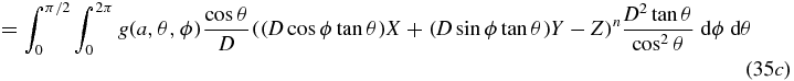
We turn now to theorem 5 which provides full consistency conditions for cone-beam projections on a plane by converting theorem 4 to the case of standard unweighted cone-beam projections.
Theorem 5. For each n = 0, 1, 2..., we define Jn in terms of g by

Then we have  with f with compactly supported in z > 0 if and only if g(a, ·, ·) has compact support for each source point a in the plane z = 0, and for each non-negative integer n,

for some homogeneous polynomial Kn(X, Y, Z) of degree n.
We first deal with the necessary conditions. Compact support of the projections is ensured by the compact support of f. Now, similar to theorem 4, it can be shown directly from  that Jn(a, X, Y) = Kn(X, Y, −axX − ayY) where Kn(X, Y, Z) is some homogeneous polynomial of degree n. The proof is straightforward and has already been given in (Clackdoyle and Desbat 2013). The polynomial Kn is given by Kn(X, Y, Z) = ∑ci, j, k Xi Yj Zk where the sum is taken over all i + j + k = n and where

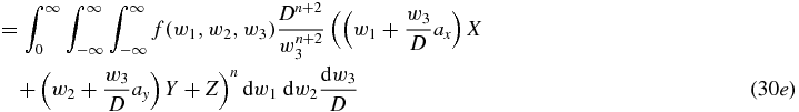
We now prove the sufficiency by appealing to theorem 4. We are given compactly supported projections g satisfying equation (33). For any choice of D > 0 we can define a function  by
by  where θ and ϕ are defined in terms of ax, ay, x, y by inverting equation (26). Compactness of the support of g(a, ·, ·) carries through to the support of
  . To apply theorem 4, we must show that
  as defined in equation (27) takes the required form of equation (28). Then for some D > 0, theorem 4 will supply a suitable f such that
  and by applying equation (26) to the definition of
  , we will obtain
  as required. Thus the task reduces to verifying that
  has the correct form. Starting with equation (27), we first change integration variables to (u, v) using (x, y) = (u, v) + (ax, ay), then (u, v) are changed to (θ, ϕ) using (u, v) = (Dcos ϕtan θ, Dsin ϕtan θ) which introduces a Jacobian term of D2 tan θ/cos 2θ. As usual, we use Z to mean −axX − ayY.


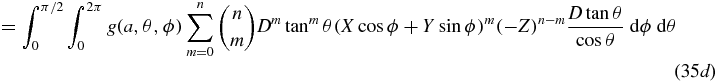


In equation (35g), we recall from the hypothesis that each Km(X, Y, Z) is a homogeneous polynomial of degree m, and therefore for each m we have that ( − Z)n − m Km(X, Y, Z) is homogeneous polynomial of degree n. Defining  we see that
  satisfies equation (28) as required, and the proof of theorem 5 is complete.
3. Applying cone-beam consistency conditions
In this section we discuss how the cone-beam consistency conditions can be applied in practice. In principle, cone-beam projections g could be converted to Jn according to equation (32) and then verified against equation (33), but we provide a more direct approach here.
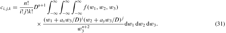
For applications of consistency conditions in medical imaging, only a finite subset of necessary conditions are invoked. We will examine the conditions on moments of the cone-beam projections. For a cone-beam projection g(a, ·, ·) we define Mk, l(a) by

For any k, l the quantity Mk, l(a) is easily calculated from the cone-beam projection g(a, ·, ·) as the weighted sum of all elements of the cone-beam projection. We will see that for consistency to hold, Mk, l(a) must be a polynomial of degree k + l in (ax, ay). The power of ax must not exceed k, and the power of ay must not exceed l. Furthermore, the polynomials 'intertwine' in an elaborate way, meaning that there are further restrictions on the pattern of the coefficients of the terms. For example, for all moments Mk, l(a) such that k + l = n, the coefficient of the high-order term of the polynomial is the same. These details will be illustrated in the examples below.
To establish these consistency conditions on Mk, l, we first note that

and recalling from theorem 5 that for consistency we have Jn(a, X, Y) = Kn(X, Y, −axX − ayY) where  for some coefficients
  and where the sum is taken over all i' + j' + k' = n. We can therefore write

and we directly find conditions on the moments Mk, l(a) by equating coefficients of Xk Yl in the right-hand sides of equations (37) and (38). The outcome is conditions on the moments Mk, l that depend on the source positions ax, ay; these conditions are also in the form of polynomials.
For n = 0 these equations give us the result that M0, 0 = c0, 0, 0. Thus the tangent-over-cosine weighted average of the cone-beam projection is constant (independent of cone-beam source position a). To simplify the notation we define C0 = c0, 0, 0. Therefore,

For n = 1 we obtain two equations: M1, 0 = −c0, 0, 1 ax + c1, 0, 0 and M0, 1 = −c0, 0, 1 ay + c0, 1, 0, which gives the following two consistency conditions on the cone-beam projections, after defining C1 = −c0, 0, 1, C2 = c1, 0, 0, and C3 = c0, 1, 0


For n = 2 we obtain  ;
;  ; M1, 1 = 2c0, 0, 2 ax ay − c0, 1, 1 ax − c1, 0, 1 ay + c1, 1, 0; which, after reassigning symbols to the six constants, leads to


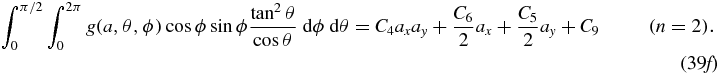
For values of n = 3 and higher, the same procedure will reveal the precise form of the polynomials of degree k + l in (ax, ay) that Mk, l(a) must take. The properties stated after equation (36) indicating the degree of the polynomials in (ax, ay) and the intertwining characteristics can be easily established by this procedure, and are already apparent in the n = 2 case above.
For the particular situation of a detector parallel to the source plane, the same procedure can be applied to the weighted cone-beam projections  to provide consistency conditions. Defining
  leads us via the same path as before to the following consistency conditions on
  :
:


These simple forms for cone-beam consistency conditions only occur when the detector is parallel to the source plane, and recalling the cosine-weighting  .
.
4. Illustration of the consistency conditions using simulated projection data
The cone-beam consistency conditions of equations (40) were verified using a computer simulation.
The geometry was chosen to have a fixed detector located 3.1 units above the plane of the simulated x-ray sources. The sources followed a circle of radius 2 about the center of the (ax, ay) system which is parallel to the (x, y) detector coordinates. The target object was a modified high-contrast version of the standard 3D Shepp-Logan phantom, centered in the system at a height of 2 units above the source plane. The geometry is illustrated in figure 4. Thirty-six cone-beam projections were simulated along the source trajectory, by mathematically computing the intersection lengths of rays passing through the component ellipses of the phantom. One ray was computed for each of the 1024 × 1024 detector pixels.

Figure 4. Circular tomosynthesis geometry. Above: the source (ax, ay) lies on a circle of radius 2 on the z = 0 plane. The center of the modified 3D Shepp Logan phantom is in the z = 2 plane, and the detector is in the z = 3.1 plane. Detector coordinates are (x, y). Below: one of the 36 simulated cone-beam projections. (Figure taken from (Clackdoyle and Desbat 2013), with permission.).
Download figure:
Standard image High-resolution imageFor this specialized geometry (fixed detector, parallel to the source plane) the simple forms of equation (40) apply. The projection measurements were first multiplied by cos θ = D/H where D = 3.1 and H2 = D2 + (x − ax)2 + (y − ay)2 to form  . The six moments corresponding to
  ,
,  ,
,  ,
,  ,
,  ,
,  were then calculated for each of the 36 simulated cone-beam projections. In principle, these six moments are polynomial functions of the source position.
For the zeroth order term (k = l = n = 0), the average of the 36 values of  was found to be 27 545.4 with a maximum deviation of 2.5, which shows
  to be constant as expected. We use
  to represent the least-squares estimate, so for the case of
  we obtained

For the first-order terms  and
and  , the least-squares fits gave


It appears that four digits of accuracy have been obtained, with machine rounding errors and low-level sampling and partial volume effects in the simulations being likely sources of the small numerical errors. So  ,
,  , and
, and  .
.
For the second-order terms, degree-2 polynomials were fit to  and
and  yielding


Therefore  ,
,  ,
,  ,
,  and
and  . Note that the leading terms agree, as expected. Finally, a least-squares fit to the 36 values of
  gave the polynomial

and we observe the coefficients  ,
,  ,
,  as predicted by the consistency conditions with only one free coefficient,
  , taking the value 0.041.
Plots of the moments and fitted polynomials are given in figures 5 and 6, to provide a graphical illustration of the consistency conditions up to order 2.

Figure 5. Moments of cone-beam projections, with polynomial fits. The horizontal axis is the projected position of the source point onto the ax or ay axis. The 36 calculated values for each moment are plotted with stars (*) and the least-squares fitted polynomial is drawn with a solid line. The results match the theory. Note that M1, 0 and M0, 1 have the same slope, as predicted. Similarly the leading term of the quadratic fits for M2, 0 and M0, 2 are the same. (Figure taken from (Clackdoyle and Desbat 2013) with permission).
Download figure:
Standard image High-resolution image
Figure 6. Polynomial fit of the moment M1, 1(ax, ay). Upper: plot of M1, 1 for the 36 cone-beam projections. Lower: plot of the fitted polynomial, restricted to the circle of raduis 2, to aid in visualization. Note that the first three coefficients found by least squares fit agree with the coefficients of the fits to M2, 0 and M0, 2 according to the predictions.
Download figure:
Standard image High-resolution image
5. Discussion and conclusions
The main contribution of this paper is the demonstration that the consistency conditions given in theorem 5, and previously announced in (Clackdoyle and Desbat 2013), are necessary and sufficient for cone-beam projections with sources on a plane. The necessary conditions are easily established directly, and the sufficient conditions are based on known sufficiency conditions for 3D parallel projections. The link from parallel to cone-beam projections was made using the theorem of Edholm and Danielsson (Edholm and Danielsson 1996), which is the key element of our demonstration.
This work represents a generalization from two dimensions to three dimensions of the fanbeam consistency conditions presented in (Clackdoyle 2013). A significant difference however, is that for parallel projections the 3D version of the consistency conditions is more elaborate than the well-known HL conditions for the 2D case. Consequently, the polynomials that arise from moments of the cone-beam projections have a complex intertwining relationship of their coefficients.
A natural question is to ask how the consistency conditions might change if the cone-beam sources were not constrained to lie in a plane. Extensions to more general source geometries using the approach of this paper would be difficult since the key theorem of Edholm and Danielsson only applies to sources in a plane. At this time we do not see a way to suitably generalize this theorem.
No specific applications of the cone-beam consistency conditions have been proposed here, however the plots of figure 5 suggest their potential. Examining the middle row of figure 5 for example, the straight lines as a function of ax and ay are parameterized by  ,
,  ,
,  which can be obtained from any three cone-beam projections with known source positions (except for certain degenerate situations such as all three sources lying in a line parallel to the x or y axes). From these straight lines, the source positions of any other projections in the plane can be determined, leading to possible applications in calibration or misalignment detection. Similarly, any displacement of the target object in a direction parallel to the source plane would move points away from the curves shown in figure 5 and allow an estimation of the extent and direction of the movement.
The cone-beam consistency conditions we have presented here are full, so in principle any other conditions can be expressed in terms of them. However, in practice, other formulations may be more convenient for applications or might lead to insights toward obtaining conditions for other source geometries than the planar one addressed in this work. Exploring different formulations of the 3D parallel-beam conditions such as by directly considering the Fourier-slice theorem is one possibility toward alternative consistency conditions.
Acknowledgments
This work was partially supported by grant ANR-12-BS01-0018 ('DROITE' project) from the Agence Nationale de la Recherche (France).